Dell PowerEdge R910 Hardware Owner's Manual - Page 154
Power Supplies
 |
View all Dell PowerEdge R910 manuals
Add to My Manuals
Save this manual to your list of manuals |
Page 154 highlights
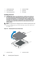
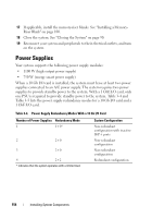
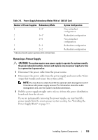
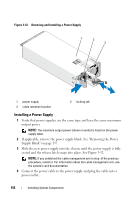
17 If applicable, install the memory-riser blanks. See "Installing a MemoryRiser Blank" on page 100. 18 Close the system. See "Closing the System" on page 90. 19 Reconnect your system and peripherals to their electrical outlets, and turn on the system. Power Supplies Your system supports the following power supply modules: • 1100 W (high output power supply) • 750 W (energy smart power supply) When a 10 Gb I/O card is installed, the system must have at least two power supplies connected to an A/C power supply. The system requires two power supplies to provide standby power to the system. With a 1 GbE I/O card, only one PSU is required to provide standby power to the system. Table 3-4 and Table 3-5 lists the power supply redundancy modes for a 10 Gb I/O card and a 1 GbE I/O card. Table 3-4. Power Supply Redundancy Modes With a 10 Gb I/O Card Number of Power Supplies Redundancy Mode 1 1+0* 2 2+0 3 2+0 4 2+2 * indicates that the system operates with a limited load. System Configuration Non-redundant configuration with inactive SFP+ ports Non-redundant configuration Non-redundant configuration Redundant configuration 154 Installing System Components
-
 1
1 -
2
-
3
-
4
-
5
-
6
-
7
-
8
-
9
-
10
-
11
-
12
-
13
-
14
-
15
-
16
-
17
-
18
-
19
-
20
-
21
-
22
-
23
-
24
-
25
-
26
-
27
-
28
-
29
-
30
-
31
-
32
-
33
-
34
-
35
-
36
-
37
-
38
-
39
-
40
-
41
-
42
-
43
-
44
-
45
-
46
-
47
-
48
-
49
-
50
-
51
-
52
-
53
-
54
-
55
-
56
-
57
-
58
-
59
-
60
-
61
-
62
-
63
-
64
-
65
-
66
-
67
-
68
-
69
-
70
-
71
-
72
-
73
-
74
-
75
-
76
-
77
-
78
-
79
-
80
-
81
-
82
-
83
-
84
-
85
-
86
-
87
-
88
-
89
-
90
-
91
-
92
-
93
-
94
-
95
-
96
-
97
-
98
-
99
-
100
-
101
-
102
-
103
-
104
-
105
-
106
-
107
-
108
-
109
-
110
-
111
-
112
-
113
-
114
-
115
-
116
-
117
-
118
-
119
-
120
-
121
-
122
-
123
-
124
-
125
-
126
-
127
-
128
-
129
-
130
-
131
-
132
-
133
-
134
-
135
-
136
-
137
-
138
-
139
-
140
-
141
-
142
-
143
-
144
-
145
-
146
-
147
-
148
-
 149
149 -
 150
150 -
 151
151 -
 152
152 -
 153
153 -
 154
154 -
 155
155 -
 156
156 -
 157
157 -
 158
158 -
 159
159 -
160
-
161
-
162
-
163
-
164
-
165
-
166
-
167
-
168
-
169
-
170
-
171
-
172
-
173
-
174
-
175
-
176
-
177
-
178
-
179
-
180
-
181
-
182
-
183
-
184
-
185
-
186
-
187
-
188
-
189
-
190
-
191
-
192
-
193
-
194
-
195
-
196
-
197
-
198
-
199
-
200
-
201
-
202
-
203
-
204
-
205
-
206
-
207
-
208
-
209
-
210
 |
 |