Epson LQ 1050 User Manual - Page 93
for each pin column. Lines 30-60 print the design that you see
 |
View all Epson LQ 1050 manuals
Add to My Manuals
Save this manual to your list of manuals |
Page 93 highlights
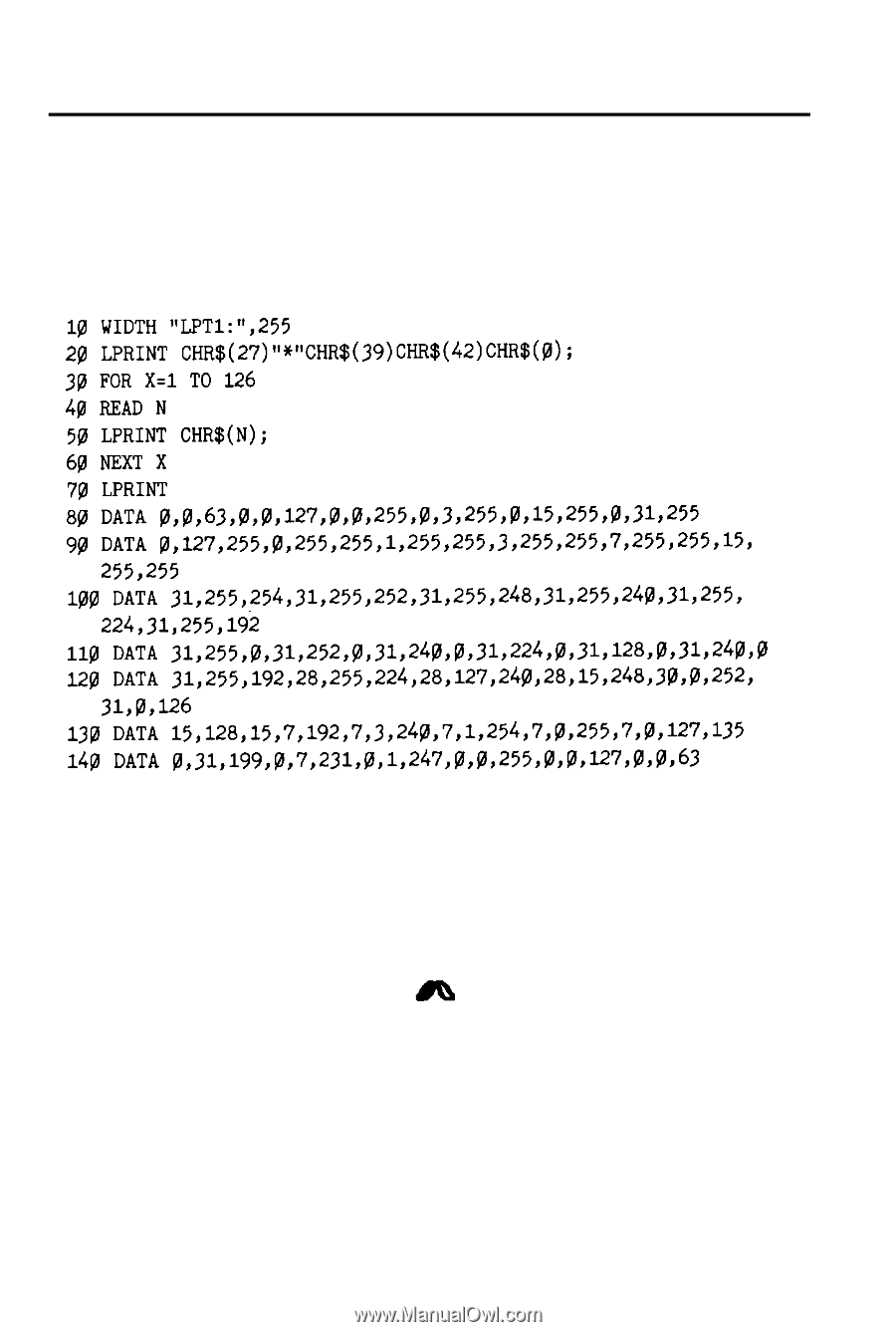
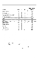
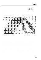
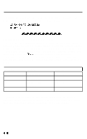
Graphics Here is the BASIC program that prints the design shown on the previous pages. Notice that the data numbers in lines 80-140 are the same numbers that you see in the last illustration. Also note that the WIDTH statement in line 10 is for IBM PC BASIC; the format may be different for your system. 10 WIDTH "LPT1:",255 20 LPRINT cHR$(27)"*"CHR$(39)CHR$(42)CHR$o; 30 FOR x=1 To 126 40 READ N 50 LPRINT CHR$(N); 60 NEXT X 70 LPRINT 80 DATA 0,0,63,0,0,127,0,0,255,0,3,255,8,15,255,0~%255 90 DATA 0,127,255,0,255,255,1,255,255,3,255,255,7,255,255,15, 255,255 100 DATA 31,255,254,31,255,252,31,255,248,31,255,240,3l,255, 224,31,255,192 110 DATA 31,255,0,31,252,0,31,240,0,31,224,0,31,12~,0,31,240~0 120 DATA 31,255,192,28,255,224,28,127,240,28,15,248,30,0,252, 31,0,126 130 DATA 15,l28,15,7,192,7,3,240,7,1,254,7,0,255~7~0~127~l35 140 DATA 0,31,199,0,7,231,0,1,247,0,0,255~0~0,~7,0,0~63 In this program, line 20 assigns the graphics option (24-pin tripledensity) with code 39. Code 42 sets the number of pin columns at 42. Lines 80-140 contain 126 bytes of data (42 pin columns x 3 bytes for each pin column). Lines 30-60 print the design that you see below. Notice that the dots overlap quite a bit. This design was printed using the triple-density 24-pin graphics option because the density is the same (180 dots to the inch) in both directions. 4-17
-
 1
1 -
2
-
3
-
4
-
5
-
6
-
7
-
8
-
9
-
10
-
11
-
12
-
13
-
14
-
15
-
16
-
17
-
18
-
19
-
20
-
21
-
22
-
23
-
24
-
25
-
26
-
27
-
28
-
29
-
30
-
31
-
32
-
33
-
34
-
35
-
36
-
37
-
38
-
39
-
40
-
41
-
42
-
43
-
44
-
45
-
46
-
47
-
48
-
49
-
50
-
51
-
52
-
53
-
54
-
55
-
56
-
57
-
58
-
59
-
60
-
61
-
62
-
63
-
64
-
65
-
66
-
67
-
68
-
69
-
70
-
71
-
72
-
73
-
74
-
75
-
76
-
77
-
78
-
79
-
80
-
81
-
82
-
83
-
84
-
85
-
86
-
87
-
 88
88 -
 89
89 -
 90
90 -
 91
91 -
 92
92 -
 93
93 -
 94
94 -
 95
95 -
 96
96 -
 97
97 -
 98
98 -
99
-
100
-
101
-
102
-
103
-
104
-
105
-
106
-
107
-
108
-
109
-
110
-
111
-
112
-
113
-
114
-
115
-
116
-
117
-
118
-
119
-
120
-
121
-
122
-
123
-
124
-
125
-
126
-
127
-
128
-
129
-
130
-
131
-
132
-
133
-
134
-
135
-
136
-
137
-
138
-
139
-
140
-
141
-
142
-
143
-
144
-
145
-
146
-
147
-
148
-
149
-
150
-
151
-
152
-
153
-
154
-
155
-
156
-
157
-
158
-
159
-
160
-
161
-
162
-
163
-
164
-
165
-
166
-
167
-
168
-
169
-
170
-
171
-
172
-
173
-
174
-
175
-
176
-
177
-
178
-
179
-
180
-
181
-
182
-
183
-
184
-
185
-
186
-
187
-
188
-
189
-
190
-
191
-
192
-
193
-
194
-
195
-
196
-
197
-
198
-
199
-
200
-
201
-
202
-
203
-
204
-
205
-
206
-
207
-
208
-
209
-
210
-
211
-
212
-
213
-
214
-
215
-
216
-
217
-
218
-
219
-
220
-
221
-
222
 |
 |