HP StorageWorks 1606 HP StorageWorks 8GB SAN Switch hardware reference guide ( - Page 40
To attach the inner rails to the FCoE Converged Network Switch, Encryption SAN Switch, or,
 |
View all HP StorageWorks 1606 manuals
Add to My Manuals
Save this manual to your list of manuals |
Page 40 highlights
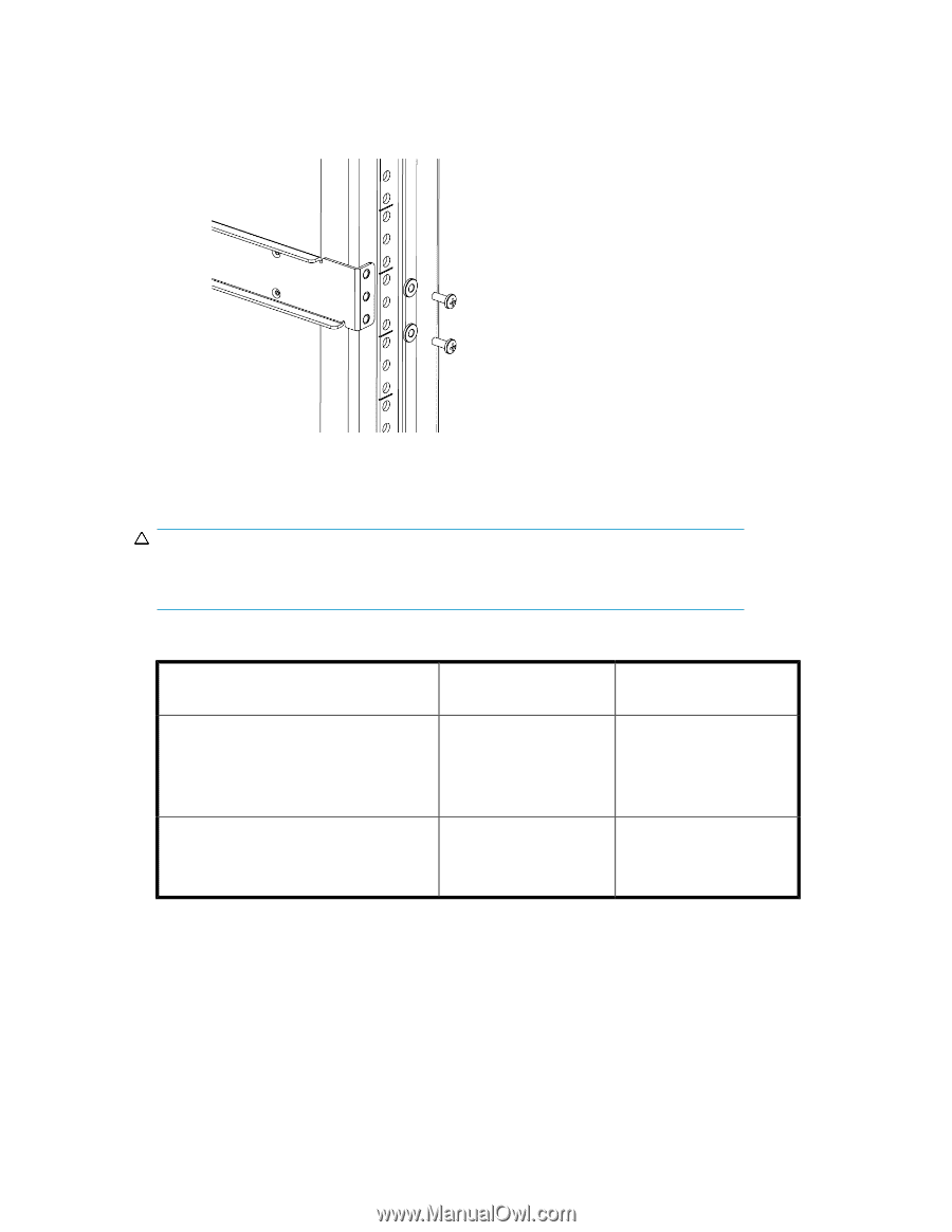
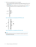
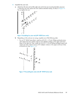
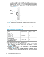
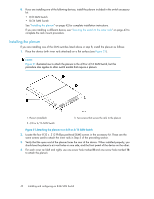
• For an HP System/e Rack, install two #10-32 x 1/2-inch Phillips panhead screws with captive star lock washers and two #10 alignment washers in the upper and lower holes on the right rail. Then, install two #10-32 x 1/2-inch Phillips panhead screws with captive star lock washers and two #10 alignment washers in the upper and lower holes on the left rail. (See Figure 18.) Figure 18 Assembling the outer rails (HP System/e rack) . 5. See Table 6 to determine the screw type and the number of screws required for your device. CAUTION: Use only the screws that have been provided. Using longer screws can cause damage to internal components. Table 6 Screws required to assemble the inner rails Device 8/8 SAN Switch 8/24 SAN Switch 8/40 SAN Switch 8/80 SAN Switch #8-32 x 5/16-inch screws Ten (five per rail) Encryption SAN Switch FCoE Converged Network Switch 1606 Extension SAN Switch Six (three per rail) #8-32 x 3/16-inch screws N/A N/A 6. Identify the screw holes to attach the inner rails to your device: • To attach the inner rails to the 8/8 or 8/24 SAN Switches, use the five screw holes marked 8. The plenum requires one screw hole marked 8 and one screw hole marked 16, as shown in Figure 21 on page 42. • To attach the inner rails to the 8/40 or 8/80 SAN Switches, use the screw holes marked 16, as shown in Figure 20 on page 41. • To attach the inner rails to the FCoE Converged Network Switch, Encryption SAN Switch, or 1606 Extension SAN Switch, use two screw holes marked R and one screw hole marked 16. 40 Installing and configuring an 8-Gb SAN Switch
-
 1
1 -
2
-
3
-
4
-
5
-
6
-
7
-
8
-
9
-
10
-
11
-
12
-
13
-
14
-
15
-
16
-
17
-
18
-
19
-
20
-
21
-
22
-
23
-
24
-
25
-
26
-
27
-
28
-
29
-
30
-
31
-
32
-
33
-
34
-
 35
35 -
 36
36 -
 37
37 -
 38
38 -
 39
39 -
 40
40 -
 41
41 -
 42
42 -
 43
43 -
 44
44 -
 45
45 -
46
-
47
-
48
-
49
-
50
-
51
-
52
-
53
-
54
-
55
-
56
-
57
-
58
-
59
-
60
-
61
-
62
-
63
-
64
-
65
-
66
-
67
-
68
-
69
-
70
-
71
-
72
-
73
-
74
-
75
-
76
-
77
-
78
-
79
-
80
-
81
-
82
-
83
-
84
-
85
-
86
-
87
-
88
-
89
-
90
-
91
-
92
-
93
-
94
-
95
-
96
-
97
-
98
-
99
-
100
-
101
-
102
-
103
-
104
-
105
-
106
-
107
-
108
-
109
-
110
-
111
-
112
-
113
-
114
-
115
-
116
-
117
-
118
-
119
-
120
 |
 |