HP StorageWorks 1606 HP StorageWorks 8GB SAN Switch hardware reference guide ( - Page 77
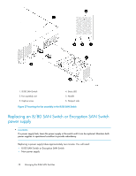
Replacing the 8/80 SAN Switch and Encryption SAN Switch fan assembly
 |
View all HP StorageWorks 1606 manuals
Add to My Manuals
Save this manual to your list of manuals |
Page 77 highlights
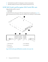
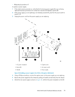
CAUTION: Disassembling any part of the fan assembly voids the part warranty and regulatory certifications. There are no user-serviceable parts inside the fan assembly. Because the cooling system relies on pressurized air, do not leave any of the fan assembly slots empty longer than two minutes while the switch is operating. If a fan assembly fails, leave it in the switch until it can be replaced. Maintain all three fan assemblies in operational condition to provide redundancy. Replacing the 8/80 SAN Switch and Encryption SAN Switch fan assembly Replacing a fan assembly takes approximately two minutes. You will need: • 8/80 SAN Switch or Encryption SAN Switch • New fan FRU assembly • Phillips-head screwdriver #1 CAUTION: The 8/80 and Encryption SAN Switches use two power cords. Disconnect both power cords before servicing. To replace a fan assembly: 1. Use a Phillips-head screwdriver to unscrew the captive screw on the fan assembly you are replacing. 2. Remove the fan assembly from the chassis by pulling the handle out and away from the chassis. 3. Install the new fan assembly in the chassis: a. Orient the new fan assembly as shown in Figure 37, with the captive screw on the right. b. Gently push the fan assembly into the chassis until it is firmly seated. CAUTION: Do not force the installation. If the fan assembly does not slide in easily, ensure that it is correctly oriented before continuing. c. Secure the fan assembly to the chassis with the captive screw. 4. Verify that the fan status LED is lit steady green to indicate normal operation (see Table 15). 5. Optionally, display the fan status using the fanshow command from the CLI (see Figure 37 for the locations of Fan assembly #1, Fan assembly #2, and Fan assembly #3). 8-Gb SAN Switch Hardware Reference Guide 77
-
 1
1 -
2
-
3
-
4
-
5
-
6
-
7
-
8
-
9
-
10
-
11
-
12
-
13
-
14
-
15
-
16
-
17
-
18
-
19
-
20
-
21
-
22
-
23
-
24
-
25
-
26
-
27
-
28
-
29
-
30
-
31
-
32
-
33
-
34
-
35
-
36
-
37
-
38
-
39
-
40
-
41
-
42
-
43
-
44
-
45
-
46
-
47
-
48
-
49
-
50
-
51
-
52
-
53
-
54
-
55
-
56
-
57
-
58
-
59
-
60
-
61
-
62
-
63
-
64
-
65
-
66
-
67
-
68
-
69
-
70
-
71
-
 72
72 -
 73
73 -
 74
74 -
 75
75 -
 76
76 -
 77
77 -
 78
78 -
 79
79 -
 80
80 -
 81
81 -
 82
82 -
83
-
84
-
85
-
86
-
87
-
88
-
89
-
90
-
91
-
92
-
93
-
94
-
95
-
96
-
97
-
98
-
99
-
100
-
101
-
102
-
103
-
104
-
105
-
106
-
107
-
108
-
109
-
110
-
111
-
112
-
113
-
114
-
115
-
116
-
117
-
118
-
119
-
120
 |
 |