HP StorageWorks 1606 HP StorageWorks 8GB SAN Switch hardware reference guide ( - Page 64
Port side LED activity for the FCoE Converged Network Switch
 |
View all HP StorageWorks 1606 manuals
Add to My Manuals
Save this manual to your list of manuals |
Page 64 highlights
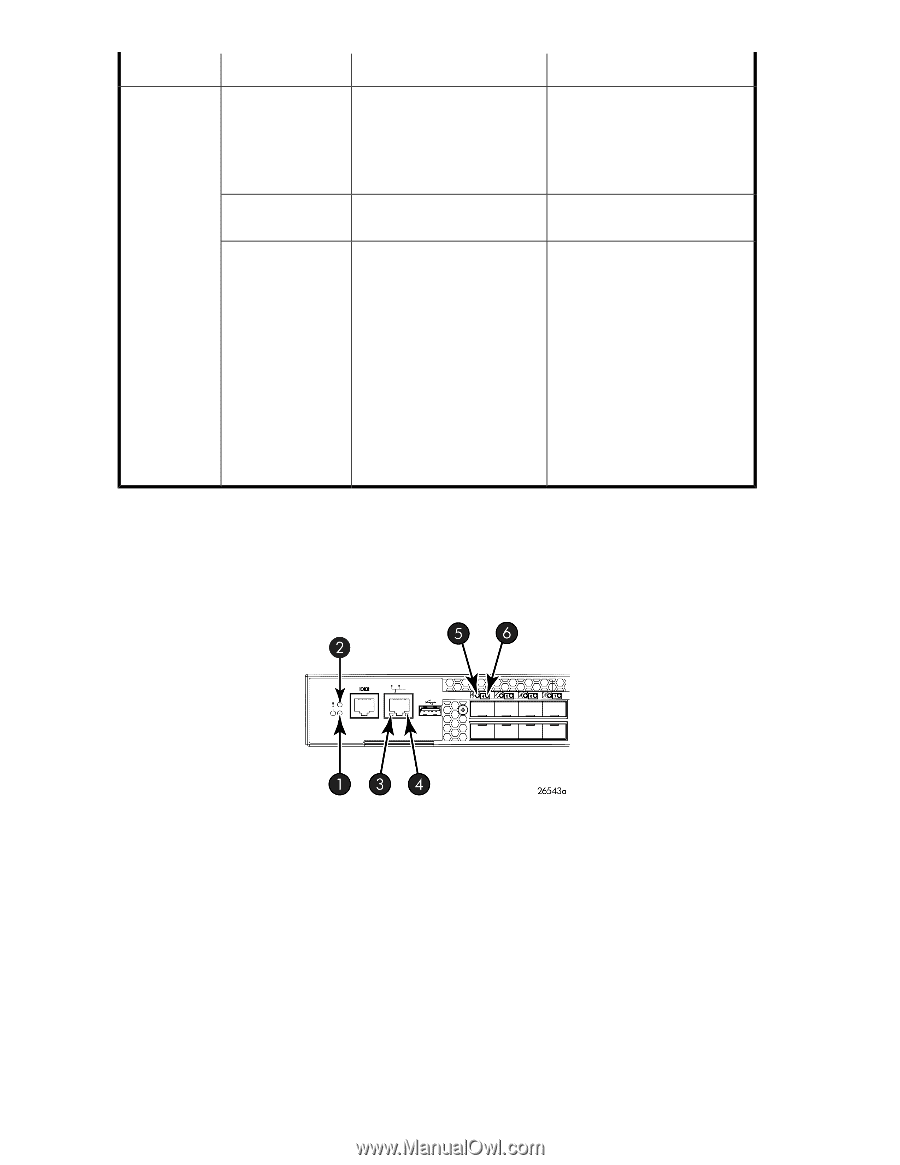
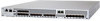
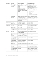
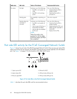
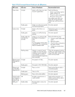
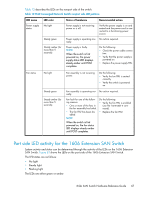
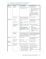
LED name Fan status LED color No light Steady green Steady amber (for more than 5 seconds) Status of hardware Indicates one of the following: • Fan FRU is not seated cor- rectly. • Fan FRU is not receiving power. Recommended action Do one of the following: • Verify that the fan FRU is seated correctly. • Verify that the switch is powered on. Fan assembly is operating nor- No action required. mally. Indicates one of the following: • Fan FRU is not seated correctly. • One or more of the fans in the fan FRU has failed. • The fan FRU was disabled by the user. NOTE: When the switch is first powered on, the fan status LED shows amber until POST has completed. Do one of the following: • Verify that the fan FRU is seated correctly. • Verify that the fan FRU is enabled (use the fanenable command). • Replace the fan FRU. Port side LED activity for the FCoE Converged Network Switch Figure 31 shows the port side of the FCoE Converged Network Switch. There are two port status LEDs above each of the top row of ports. The left LED is for the top port, and the right LED is for the bottom port. See Figure 7 on page 21 for the locations of the GbE and FC ports. 1. System power LED 2. System status LED 3. Ethernet speed LED 4. Ethernet link LED 5. CEE port status LED (port 0) 6. CEE port status LED (port 4) Figure 31 Port side LEDs on the FCoE Converged Network Switch . Table 11 describes the port side LEDs and the recommended actions. 64 Managing the 8-Gb SAN Switches
-
 1
1 -
2
-
3
-
4
-
5
-
6
-
7
-
8
-
9
-
10
-
11
-
12
-
13
-
14
-
15
-
16
-
17
-
18
-
19
-
20
-
21
-
22
-
23
-
24
-
25
-
26
-
27
-
28
-
29
-
30
-
31
-
32
-
33
-
34
-
35
-
36
-
37
-
38
-
39
-
40
-
41
-
42
-
43
-
44
-
45
-
46
-
47
-
48
-
49
-
50
-
51
-
52
-
53
-
54
-
55
-
56
-
57
-
58
-
 59
59 -
 60
60 -
 61
61 -
 62
62 -
 63
63 -
 64
64 -
 65
65 -
 66
66 -
 67
67 -
 68
68 -
 69
69 -
70
-
71
-
72
-
73
-
74
-
75
-
76
-
77
-
78
-
79
-
80
-
81
-
82
-
83
-
84
-
85
-
86
-
87
-
88
-
89
-
90
-
91
-
92
-
93
-
94
-
95
-
96
-
97
-
98
-
99
-
100
-
101
-
102
-
103
-
104
-
105
-
106
-
107
-
108
-
109
-
110
-
111
-
112
-
113
-
114
-
115
-
116
-
117
-
118
-
119
-
120
 |
 |