HP StorageWorks 1606 HP StorageWorks 8GB SAN Switch hardware reference guide ( - Page 42
Installing the plenum, 24 SAN Switch
 |
View all HP StorageWorks 1606 manuals
Add to My Manuals
Save this manual to your list of manuals |
Page 42 highlights
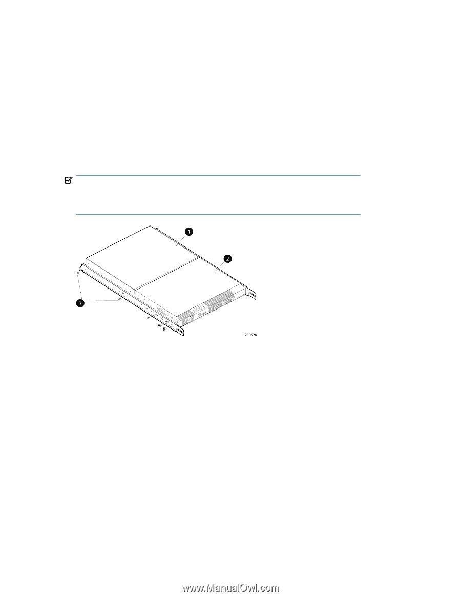
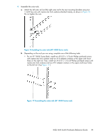
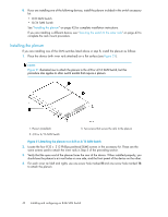
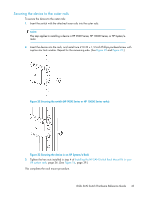
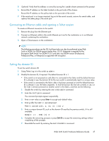
8. If you are installing one of the following devices, install the plenum included in the switch accessory kit: • 8/8 SAN Switch • 8/24 SAN Switch See "Installing the plenum" on page 42 for complete installation instructions. If you are installing a different device, see "Securing the switch to the outer rails" on page 43 to complete the rack mount procedure. Installing the plenum If you are installing one of the SAN switches listed above in step 8, install the plenum as follows: 1. Place the device (with inner rails attached) on a flat surface (see Figure 21). NOTE: Figure 21 illustrates how to attach the plenum to the 4/8 or 4/16 SAN Switch, but this procedure also applies to other switch models that require a plenum. 1. Plenum (installed) 2. 4/8 or 4/16 SAN Switch 3. Two screws that secure the rails to the plenum Figure 21 Attaching the plenum to a 4/8 or 4/16 SAN Switch . 2. Locate the four 8-32 x .312 Phillips panhead SEMS screws in the accessory kit. These are the same screws used to attach the inner rails in Step 5 of the preceding section. 3. Verify that the open end of the plenum faces the rear of the device. When installed properly, you should see the plenum's air vent holes on one side, and the front panel of the device on the other. 4. For each inner rail (left and right), use one screw hole marked 8 and one screw hole marked 16 to attach the plenum. 42 Installing and configuring an 8-Gb SAN Switch
-
 1
1 -
2
-
3
-
4
-
5
-
6
-
7
-
8
-
9
-
10
-
11
-
12
-
13
-
14
-
15
-
16
-
17
-
18
-
19
-
20
-
21
-
22
-
23
-
24
-
25
-
26
-
27
-
28
-
29
-
30
-
31
-
32
-
33
-
34
-
35
-
36
-
 37
37 -
 38
38 -
 39
39 -
 40
40 -
 41
41 -
 42
42 -
 43
43 -
 44
44 -
 45
45 -
 46
46 -
 47
47 -
48
-
49
-
50
-
51
-
52
-
53
-
54
-
55
-
56
-
57
-
58
-
59
-
60
-
61
-
62
-
63
-
64
-
65
-
66
-
67
-
68
-
69
-
70
-
71
-
72
-
73
-
74
-
75
-
76
-
77
-
78
-
79
-
80
-
81
-
82
-
83
-
84
-
85
-
86
-
87
-
88
-
89
-
90
-
91
-
92
-
93
-
94
-
95
-
96
-
97
-
98
-
99
-
100
-
101
-
102
-
103
-
104
-
105
-
106
-
107
-
108
-
109
-
110
-
111
-
112
-
113
-
114
-
115
-
116
-
117
-
118
-
119
-
120
 |
 |