HP StorageWorks 1606 HP StorageWorks 8GB SAN Switch hardware reference guide ( - Page 45
Powering off the 8-Gb SAN Switch, Making a serial connection, For the 8/40 and 8/80 SAN Switches
 |
View all HP StorageWorks 1606 manuals
Add to My Manuals
Save this manual to your list of manuals |
Page 45 highlights
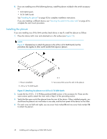
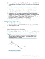
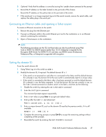
1. Connect the power cords to a power inlet on the switch and to a power source. Verify that the cords use a minimum service loop of 15.2 cm (6 inches) to avoid stress. The switch powers on automatically; there is no ON/OFF switch. To power off, remove the power cord from the power source. CAUTION: To protect against AC failure on the 8/40 and 8/80 SAN Switches, Encryption SAN Switch, FCoE Converged Network Switch, and 1606 Extension SAN Switch, connect each power cord to an outlet on separate circuits. 2. For the 8/40 and 8/80 SAN Switches, Encryption SAN Switch, FCoE Converged Network Switch, and 1606 Extension SAN Switch, set the two AC switches to the ON position (1). Power is supplied to the switch as soon as the first power supply is connected and turned on. The power supply LEDs display amber until POST completes, and then change to green. The switch usually requires from 1 to 3 minutes to boot and complete POST. 3. After POST completes, verify that the switch Power and Status LEDs light are green. Powering off the 8-Gb SAN Switch 1. Execute the sysshutdown command. This command shuts down the key processors and powers off the switch. All LEDs extinguish. 2. Set each AC power switch to O. Making a serial connection All basic configuration tasks require a serial connection. 1. Connect the serial cable to an RS-232 serial port on the workstation, as shown in Figure 24. Figure 24 shows the 8/40 SAN Switch; however, the procedure is similar for all SAN Switches. NOTE: If the serial port on the workstation uses an RJ-45 connector instead of an RS-232 connector, remove the adapter on the end of the serial cable, and insert the exposed RJ-45 connector into the RJ-45 serial port on the workstation. Figure 24 Connecting the serial cable . 8-Gb SAN Switch Hardware Reference Guide 45
-
 1
1 -
2
-
3
-
4
-
5
-
6
-
7
-
8
-
9
-
10
-
11
-
12
-
13
-
14
-
15
-
16
-
17
-
18
-
19
-
20
-
21
-
22
-
23
-
24
-
25
-
26
-
27
-
28
-
29
-
30
-
31
-
32
-
33
-
34
-
35
-
36
-
37
-
38
-
39
-
 40
40 -
 41
41 -
 42
42 -
 43
43 -
 44
44 -
 45
45 -
 46
46 -
 47
47 -
 48
48 -
 49
49 -
 50
50 -
51
-
52
-
53
-
54
-
55
-
56
-
57
-
58
-
59
-
60
-
61
-
62
-
63
-
64
-
65
-
66
-
67
-
68
-
69
-
70
-
71
-
72
-
73
-
74
-
75
-
76
-
77
-
78
-
79
-
80
-
81
-
82
-
83
-
84
-
85
-
86
-
87
-
88
-
89
-
90
-
91
-
92
-
93
-
94
-
95
-
96
-
97
-
98
-
99
-
100
-
101
-
102
-
103
-
104
-
105
-
106
-
107
-
108
-
109
-
110
-
111
-
112
-
113
-
114
-
115
-
116
-
117
-
118
-
119
-
120
 |
 |