HP StorageWorks 1606 HP StorageWorks 8GB SAN Switch hardware reference guide ( - Page 67
Port side LED activity for the 1606 Extension SAN Switch
 |
View all HP StorageWorks 1606 manuals
Add to My Manuals
Save this manual to your list of manuals |
Page 67 highlights
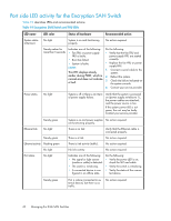
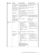
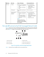
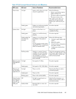
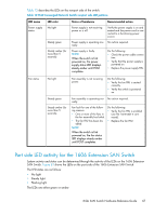
Table 12 describes the LEDs on the nonport side of the switch. Table 12 FCoE Converged Network Switch nonport side LED patterns LED name Power supply status LED color No light Steady green Steady amber (for more than 5 seconds) Status of hardware Recommended action Power supply is not receiving power or is off. Verify the power supply is on and seated and the power cord is connected to a functioning power source. Power supply is operating nor- No action required. mally. Power supply is faulty. NOTE: When the switch is first powered on, the power supply status LED displays steady amber until POST completes. Do the following: • Check the power cable connection. • Verify that the power supply is powered on. • Replace the power supply FRU. Fan status No light Steady green Steady amber (for more than 5 seconds) Fan assembly is not receiving power. Do the following: • Verify the fan FRU is seated correctly. • Verify the switch is powered on. Fan assembly is operating nor- No action required. mally. Fan fault for one of the following reasons: • One or more of the fans in the fan assembly has failed. • The fan FRU has been disabled. NOTE: When the switch is first powered on, the fan status LED displays steady amber until POST completes. Do the following: • Verify the fan FRU is enabled (use the fanenable command). • Replace the fan FRU. Port side LED activity for the 1606 Extension SAN Switch System activity and status can be determined through the activity of the LEDs on the 1606 Extension SAN Switch. Figure 33 shows the LEDs on the port side of the 1606 Extension SAN Switch. The LED states are as follows: • No light • Steady light • Flashing light The LEDs are either green or amber. 8-Gb SAN Switch Hardware Reference Guide 67
-
 1
1 -
2
-
3
-
4
-
5
-
6
-
7
-
8
-
9
-
10
-
11
-
12
-
13
-
14
-
15
-
16
-
17
-
18
-
19
-
20
-
21
-
22
-
23
-
24
-
25
-
26
-
27
-
28
-
29
-
30
-
31
-
32
-
33
-
34
-
35
-
36
-
37
-
38
-
39
-
40
-
41
-
42
-
43
-
44
-
45
-
46
-
47
-
48
-
49
-
50
-
51
-
52
-
53
-
54
-
55
-
56
-
57
-
58
-
59
-
60
-
61
-
 62
62 -
 63
63 -
 64
64 -
 65
65 -
 66
66 -
 67
67 -
 68
68 -
 69
69 -
 70
70 -
 71
71 -
 72
72 -
73
-
74
-
75
-
76
-
77
-
78
-
79
-
80
-
81
-
82
-
83
-
84
-
85
-
86
-
87
-
88
-
89
-
90
-
91
-
92
-
93
-
94
-
95
-
96
-
97
-
98
-
99
-
100
-
101
-
102
-
103
-
104
-
105
-
106
-
107
-
108
-
109
-
110
-
111
-
112
-
113
-
114
-
115
-
116
-
117
-
118
-
119
-
120
 |
 |
