HP StorageWorks 1606 HP StorageWorks 8GB SAN Switch hardware reference guide ( - Page 62
Port side LED activity for the Encryption SAN Switch
 |
View all HP StorageWorks 1606 manuals
Add to My Manuals
Save this manual to your list of manuals |
Page 62 highlights
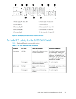
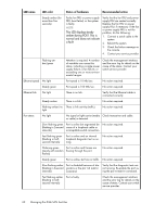
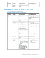
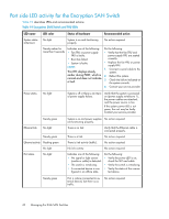
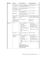
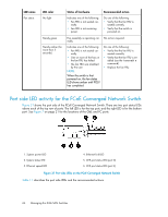
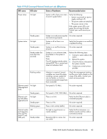
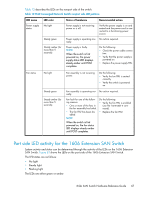
Port side LED activity for the Encryption SAN Switch Table 10 describes LEDs and recommended actions. Table 10 Encryption SAN Switch and FRU LEDs LED name System status (Attention) LED color Status of hardware Recommended action No light System is on and functioning properly No action required. Steady amber for more than 5 seconds Indicates one of the following: • Fan FRU or power supply FRU is faulty. • Boot has failed. • System is faulty. NOTE: This LED displays steady amber during POST, which is normal and does not indicate a fault. Do the following: • Verify that the fan FRU and power supply FRU are seated correctly. • Replace the fan FRU or power supply FRU. 1. Connect a serial cable to the system. 2. Reboot the system. 3. Check the failure indicated on the system console. 4. Contact your service provider. Power status No light System is off or there is an internal power supply failure. Verify that the system is powered on (power supply switches to 1), the power cables are attached, and the power source is live. If the system power LED is not green, the unit may be faulty. Contact your service provider. Steady green Ethernet link No light Steady green Ethernet activity Flashing green No light Port status No light System is on and power supplies No action required. are functioning properly. There is no link. Verify that the Ethernet cable is connected properly. There is a link. No action required. There is link activity (traffic). No action required. No link activity No action required. Indicates one of the following: • No signal or light carrier (media or cable) is detected. • The switch is initializing. • A connected device is configured in an offline state. Do the following: • Verify the power LED is on; check the SFP and cable. • Verify the switch is initializing. • Verify the status of the connected device. Steady green Port is online (connected to external device), but there is no traffic. No action required. 62 Managing the 8-Gb SAN Switches
-
 1
1 -
2
-
3
-
4
-
5
-
6
-
7
-
8
-
9
-
10
-
11
-
12
-
13
-
14
-
15
-
16
-
17
-
18
-
19
-
20
-
21
-
22
-
23
-
24
-
25
-
26
-
27
-
28
-
29
-
30
-
31
-
32
-
33
-
34
-
35
-
36
-
37
-
38
-
39
-
40
-
41
-
42
-
43
-
44
-
45
-
46
-
47
-
48
-
49
-
50
-
51
-
52
-
53
-
54
-
55
-
56
-
 57
57 -
 58
58 -
 59
59 -
 60
60 -
 61
61 -
 62
62 -
 63
63 -
 64
64 -
 65
65 -
 66
66 -
 67
67 -
68
-
69
-
70
-
71
-
72
-
73
-
74
-
75
-
76
-
77
-
78
-
79
-
80
-
81
-
82
-
83
-
84
-
85
-
86
-
87
-
88
-
89
-
90
-
91
-
92
-
93
-
94
-
95
-
96
-
97
-
98
-
99
-
100
-
101
-
102
-
103
-
104
-
105
-
106
-
107
-
108
-
109
-
110
-
111
-
112
-
113
-
114
-
115
-
116
-
117
-
118
-
119
-
120
 |
 |