Kyocera C270N Operation Guide - Page 131
Parallel Interface (EP C270N only), Communication Modes, Interface Signals
 |
UPC - 632983011935
View all Kyocera C270N manuals
Add to My Manuals
Save this manual to your list of manuals |
Page 131 highlights
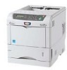
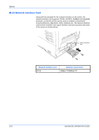
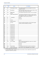
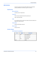
Computer Interface Parallel Interface (EP C270N only) Communication Modes The printer provides high-speed data transmission on a parallel interface. You can select the parallel interface communication mode from the operation panel. To change communication mode, see Changing Parallel Interface Mode (EP C270N only) on page 2-29. NOTE: Use a parallel interface cable that complies with the IEEE 1284 standard. You can choose from four communication modes: Communication Mode Auto (default) Nibble High-speed Normal Reception High-speed/ECP High-speed High-speed Normal Transmission Nibble/ECP Nibble - - Interface Signals Table shows the connector pins and corresponding input and output signals of the parallel interface. Explanation of each signal is also given in the table. The description in [ ] indicates signal names in Auto mode and Nibble (high) mode (IEEE 1284-compliant). In Auto and Nibble modes, these signals are bidirectional. Pin 1 In or out In Signal Strobe† [nStrobe] 2 In Data 0 [Data 1] 3 In Data 1 [Data 2] 4 In Data 2 [Data 3] 5 In Data 3 [Data 4] 6 In Data 4 [Data 5] 7 In Data 5 [Data 6] 8 In Data 6 [Data 7] 9 In Data 7 [Data 8] Description A negative-going-strobe pulse causes the printer to read and latch the data on the Data 0 [1] to Data 7 [8] signal lines. These eight signals form one byte of data sent from host computer to printer. Data 7 [8] is the most significant bit. ADVANCED OPERATION GUIDE 4-3
-
 1
1 -
2
-
3
-
4
-
5
-
6
-
7
-
8
-
9
-
10
-
11
-
12
-
13
-
14
-
15
-
16
-
17
-
18
-
19
-
20
-
21
-
22
-
23
-
24
-
25
-
26
-
27
-
28
-
29
-
30
-
31
-
32
-
33
-
34
-
35
-
36
-
37
-
38
-
39
-
40
-
41
-
42
-
43
-
44
-
45
-
46
-
47
-
48
-
49
-
50
-
51
-
52
-
53
-
54
-
55
-
56
-
57
-
58
-
59
-
60
-
61
-
62
-
63
-
64
-
65
-
66
-
67
-
68
-
69
-
70
-
71
-
72
-
73
-
74
-
75
-
76
-
77
-
78
-
79
-
80
-
81
-
82
-
83
-
84
-
85
-
86
-
87
-
88
-
89
-
90
-
91
-
92
-
93
-
94
-
95
-
96
-
97
-
98
-
99
-
100
-
101
-
102
-
103
-
104
-
105
-
106
-
107
-
108
-
109
-
110
-
111
-
112
-
113
-
114
-
115
-
116
-
117
-
118
-
119
-
120
-
121
-
122
-
123
-
124
-
125
-
 126
126 -
 127
127 -
 128
128 -
 129
129 -
 130
130 -
 131
131 -
 132
132 -
 133
133 -
 134
134 -
 135
135 -
 136
136 -
137
-
138
-
139
-
140
-
141
-
142
-
143
-
144
-
145
-
146
-
147
-
148
-
149
-
150
 |
 |