Kyocera C270N Operation Guide - Page 134
Serial Interface (EP C270N only), Interface Signals, Interface voltage levels
 |
UPC - 632983011935
View all Kyocera C270N manuals
Add to My Manuals
Save this manual to your list of manuals |
Page 134 highlights
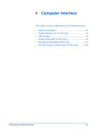
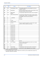
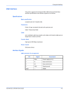
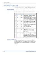
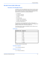
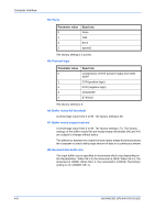
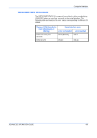
Computer Interface Serial Interface (EP C270N only) Installing the optional serial interface board kit (IB-11) in the printer enables connection to a computer with an RS-232C standard serial interface. Interface Signals The table below shows the pins and corresponding input and output signals of the RS-232C interface connector. Pin In or out Signal Description 1- 2 Out 3 In 4 Out 5 In 6 In 7- 20 Out FG TXD RXD RTS CTS DSR SG DTR Frame Ground. This pin is connected directly to the printer frame. Transmit Data. This pin is used to output asynchronous data sent from the printer to the computer. This signal is often used in handshaking. Receive Data. This pin is used to input serial asynchronous data sent from the computer to the printer. Request To Send. This output is always high (above 3 volts). Clear To Send. Not used. Data Set Ready. Not used. Signal Ground. This pin is used to establish a common reference level for the voltages of all signals other than Frame Ground. Data Terminal Ready. This pin is used to notify the status of the printer buffer (i.e., nearly full or nearly empty) when handshaking is used. The pin goes high (above 3 volts) when the buffer is able to accept more data. Interface voltage levels The voltage levels of the interface signals conform to EIA RS-232C specifications. The voltage level of SPACE is 3 to 15 volts. The voltage level of MARK is -3 to -15 volts. Voltages between -3 and 3 volts are undefined. 4-6 ADVANCED OPERATION GUIDE
-
 1
1 -
2
-
3
-
4
-
5
-
6
-
7
-
8
-
9
-
10
-
11
-
12
-
13
-
14
-
15
-
16
-
17
-
18
-
19
-
20
-
21
-
22
-
23
-
24
-
25
-
26
-
27
-
28
-
29
-
30
-
31
-
32
-
33
-
34
-
35
-
36
-
37
-
38
-
39
-
40
-
41
-
42
-
43
-
44
-
45
-
46
-
47
-
48
-
49
-
50
-
51
-
52
-
53
-
54
-
55
-
56
-
57
-
58
-
59
-
60
-
61
-
62
-
63
-
64
-
65
-
66
-
67
-
68
-
69
-
70
-
71
-
72
-
73
-
74
-
75
-
76
-
77
-
78
-
79
-
80
-
81
-
82
-
83
-
84
-
85
-
86
-
87
-
88
-
89
-
90
-
91
-
92
-
93
-
94
-
95
-
96
-
97
-
98
-
99
-
100
-
101
-
102
-
103
-
104
-
105
-
106
-
107
-
108
-
109
-
110
-
111
-
112
-
113
-
114
-
115
-
116
-
117
-
118
-
119
-
120
-
121
-
122
-
123
-
124
-
125
-
126
-
127
-
128
-
 129
129 -
 130
130 -
 131
131 -
 132
132 -
 133
133 -
 134
134 -
 135
135 -
 136
136 -
 137
137 -
 138
138 -
 139
139 -
140
-
141
-
142
-
143
-
144
-
145
-
146
-
147
-
148
-
149
-
150
 |
 |