Lexmark E238 Service Manual - Page 123
Main motor service check, Action, Warning
 |
View all Lexmark E238 manuals
Add to My Manuals
Save this manual to your list of manuals |
Page 123 highlights
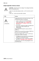
Main motor service check 4511-xxx FRU Main motor cable LVPS/HVPS Controller card Warning: Do not replace the operator panel and controller card at the same time. Each card contains the printer settings. When either of these cards is new, it obtains the settings from the other card. Settings are lost when both are new and replaced at the same time. Action Turn off the printer, and unplug the main motor cable at J8. Turn on the printer, and check for the following voltages at J8: J8 pins Pins 1-4 Pin 6 Pins 7-9 Voltages Approx. +3.3 V dc Approx. +5 V dc 10 V dc-24 V dc Verify ground at pin 5 for both the card and cable. • If these voltages are correct, check the main motor cable for continuity. - Remove rear cover to access connector on motor. - If continuity exists on each wire, call next level of service. - If continuity does not exist on one or more of the wires, replace the motor cable. • If these voltages are not correct, see "Controller card connector pin values" on page 5-4, or replace the controller card. See "Controller card removal" on page 4-15. Note: The main motor is not a service part. Diagnostics-all models 2-91
-
 1
1 -
2
-
3
-
4
-
5
-
6
-
7
-
8
-
9
-
10
-
11
-
12
-
13
-
14
-
15
-
16
-
17
-
18
-
19
-
20
-
21
-
22
-
23
-
24
-
25
-
26
-
27
-
28
-
29
-
30
-
31
-
32
-
33
-
34
-
35
-
36
-
37
-
38
-
39
-
40
-
41
-
42
-
43
-
44
-
45
-
46
-
47
-
48
-
49
-
50
-
51
-
52
-
53
-
54
-
55
-
56
-
57
-
58
-
59
-
60
-
61
-
62
-
63
-
64
-
65
-
66
-
67
-
68
-
69
-
70
-
71
-
72
-
73
-
74
-
75
-
76
-
77
-
78
-
79
-
80
-
81
-
82
-
83
-
84
-
85
-
86
-
87
-
88
-
89
-
90
-
91
-
92
-
93
-
94
-
95
-
96
-
97
-
98
-
99
-
100
-
101
-
102
-
103
-
104
-
105
-
106
-
107
-
108
-
109
-
110
-
111
-
112
-
113
-
114
-
115
-
116
-
117
-
 118
118 -
 119
119 -
 120
120 -
 121
121 -
 122
122 -
 123
123 -
 124
124 -
 125
125 -
 126
126 -
 127
127 -
 128
128 -
129
-
130
-
131
-
132
-
133
-
134
-
135
-
136
-
137
-
138
-
139
-
140
-
141
-
142
-
143
-
144
-
145
-
146
-
147
-
148
-
149
-
150
-
151
-
152
-
153
-
154
-
155
-
156
-
157
-
158
-
159
-
160
-
161
-
162
-
163
-
164
-
165
-
166
-
167
-
168
-
169
-
170
-
171
-
172
-
173
-
174
-
175
-
176
-
177
-
178
-
179
-
180
-
181
-
182
-
183
-
184
-
185
-
186
-
187
-
188
-
189
-
190
-
191
-
192
-
193
-
194
-
195
-
196
-
197
-
198
-
199
-
200
-
201
-
202
-
203
-
204
-
205
-
206
-
207
-
208
-
209
-
210
-
211
-
212
-
213
-
214
-
215
-
216
-
217
-
218
-
219
-
220
-
221
-
222
-
223
-
224
-
225
-
226
-
227
-
228
-
229
-
230
-
231
-
232
-
233
-
234
-
235
-
236
-
237
-
238
-
239
-
240
-
241
-
242
-
243
-
244
-
245
-
246
-
247
-
248
-
249
-
250
-
251
-
252
-
253
-
254
-
255
-
256
-
257
-
258
-
259
 |
 |
