Lexmark E238 Service Manual - Page 212
Input roller clutch and lever removal (autocompensator clutch
 |
View all Lexmark E238 manuals
Add to My Manuals
Save this manual to your list of manuals |
Page 212 highlights
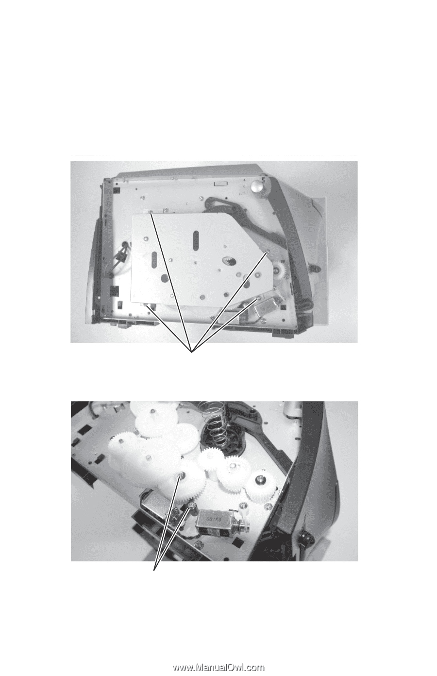
4511-xxx Input roller clutch and lever removal (autocompensator clutch) 1. Remove the left side cover. See "Left side cover removal" on page 4-9. 2. Place the printer on its right side. Protect the cover from being marred. 3. Remove four screws in the gear train metal cover. A 4. Remove the screws (B) from the shaft of the input roller clutch assembly and the lever (pawl). B 5. Remove the clutch assembly and the lever. If the pieces come apart, they can be easily reassembled if necessary. 4-34 Service Manual
-
 1
1 -
2
-
3
-
4
-
5
-
6
-
7
-
8
-
9
-
10
-
11
-
12
-
13
-
14
-
15
-
16
-
17
-
18
-
19
-
20
-
21
-
22
-
23
-
24
-
25
-
26
-
27
-
28
-
29
-
30
-
31
-
32
-
33
-
34
-
35
-
36
-
37
-
38
-
39
-
40
-
41
-
42
-
43
-
44
-
45
-
46
-
47
-
48
-
49
-
50
-
51
-
52
-
53
-
54
-
55
-
56
-
57
-
58
-
59
-
60
-
61
-
62
-
63
-
64
-
65
-
66
-
67
-
68
-
69
-
70
-
71
-
72
-
73
-
74
-
75
-
76
-
77
-
78
-
79
-
80
-
81
-
82
-
83
-
84
-
85
-
86
-
87
-
88
-
89
-
90
-
91
-
92
-
93
-
94
-
95
-
96
-
97
-
98
-
99
-
100
-
101
-
102
-
103
-
104
-
105
-
106
-
107
-
108
-
109
-
110
-
111
-
112
-
113
-
114
-
115
-
116
-
117
-
118
-
119
-
120
-
121
-
122
-
123
-
124
-
125
-
126
-
127
-
128
-
129
-
130
-
131
-
132
-
133
-
134
-
135
-
136
-
137
-
138
-
139
-
140
-
141
-
142
-
143
-
144
-
145
-
146
-
147
-
148
-
149
-
150
-
151
-
152
-
153
-
154
-
155
-
156
-
157
-
158
-
159
-
160
-
161
-
162
-
163
-
164
-
165
-
166
-
167
-
168
-
169
-
170
-
171
-
172
-
173
-
174
-
175
-
176
-
177
-
178
-
179
-
180
-
181
-
182
-
183
-
184
-
185
-
186
-
187
-
188
-
189
-
190
-
191
-
192
-
193
-
194
-
195
-
196
-
197
-
198
-
199
-
200
-
201
-
202
-
203
-
204
-
205
-
206
-
 207
207 -
 208
208 -
 209
209 -
 210
210 -
 211
211 -
 212
212 -
 213
213 -
 214
214 -
 215
215 -
 216
216 -
 217
217 -
218
-
219
-
220
-
221
-
222
-
223
-
224
-
225
-
226
-
227
-
228
-
229
-
230
-
231
-
232
-
233
-
234
-
235
-
236
-
237
-
238
-
239
-
240
-
241
-
242
-
243
-
244
-
245
-
246
-
247
-
248
-
249
-
250
-
251
-
252
-
253
-
254
-
255
-
256
-
257
-
258
-
259
 |
 |
4511-xxx
4-34
Service Manual
Input roller clutch and lever removal (autocompensator
clutch)
1.
Remove the left side cover. See
“Left side cover removal” on
page 4-9
.
2.
Place the printer on its right side. Protect the cover from being marred.
3.
Remove four screws in the gear train metal cover.
4.
Remove the screws (B) from the shaft of the input roller clutch
assembly and the lever (pawl).
5.
Remove the clutch assembly and the lever. If the pieces come apart,
they can be easily reassembled if necessary.
A
B