Lexmark E238 Service Manual - Page 217
LCD operator panel removal, LCD bezel removal
 |
View all Lexmark E238 manuals
Add to My Manuals
Save this manual to your list of manuals |
Page 217 highlights
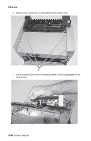
4511-xxx Installation note: The clear lens has a molded-in triangle (C). Install the lens so the triangle is positioned toward the LCD buttons. Be sure the lens is free of debris and fingerprints before installing. C LCD operator panel removal 1. Remove the LCD bezel. See "LCD bezel removal" on page 4-37. 2. Remove the two screws (A) holding the LCD assembly to the front access cover. 3. Unlatch the LCD display (left and right side of the LCD). A 4. Carefully pull the LCD assembly away from the front access cover. 5. Disconnect the LCD cable. Repair information 4-39
-
 1
1 -
2
-
3
-
4
-
5
-
6
-
7
-
8
-
9
-
10
-
11
-
12
-
13
-
14
-
15
-
16
-
17
-
18
-
19
-
20
-
21
-
22
-
23
-
24
-
25
-
26
-
27
-
28
-
29
-
30
-
31
-
32
-
33
-
34
-
35
-
36
-
37
-
38
-
39
-
40
-
41
-
42
-
43
-
44
-
45
-
46
-
47
-
48
-
49
-
50
-
51
-
52
-
53
-
54
-
55
-
56
-
57
-
58
-
59
-
60
-
61
-
62
-
63
-
64
-
65
-
66
-
67
-
68
-
69
-
70
-
71
-
72
-
73
-
74
-
75
-
76
-
77
-
78
-
79
-
80
-
81
-
82
-
83
-
84
-
85
-
86
-
87
-
88
-
89
-
90
-
91
-
92
-
93
-
94
-
95
-
96
-
97
-
98
-
99
-
100
-
101
-
102
-
103
-
104
-
105
-
106
-
107
-
108
-
109
-
110
-
111
-
112
-
113
-
114
-
115
-
116
-
117
-
118
-
119
-
120
-
121
-
122
-
123
-
124
-
125
-
126
-
127
-
128
-
129
-
130
-
131
-
132
-
133
-
134
-
135
-
136
-
137
-
138
-
139
-
140
-
141
-
142
-
143
-
144
-
145
-
146
-
147
-
148
-
149
-
150
-
151
-
152
-
153
-
154
-
155
-
156
-
157
-
158
-
159
-
160
-
161
-
162
-
163
-
164
-
165
-
166
-
167
-
168
-
169
-
170
-
171
-
172
-
173
-
174
-
175
-
176
-
177
-
178
-
179
-
180
-
181
-
182
-
183
-
184
-
185
-
186
-
187
-
188
-
189
-
190
-
191
-
192
-
193
-
194
-
195
-
196
-
197
-
198
-
199
-
200
-
201
-
202
-
203
-
204
-
205
-
206
-
207
-
208
-
209
-
210
-
211
-
 212
212 -
 213
213 -
 214
214 -
 215
215 -
 216
216 -
 217
217 -
 218
218 -
 219
219 -
 220
220 -
 221
221 -
 222
222 -
223
-
224
-
225
-
226
-
227
-
228
-
229
-
230
-
231
-
232
-
233
-
234
-
235
-
236
-
237
-
238
-
239
-
240
-
241
-
242
-
243
-
244
-
245
-
246
-
247
-
248
-
249
-
250
-
251
-
252
-
253
-
254
-
255
-
256
-
257
-
258
-
259
 |
 |

4511-xxx
Repair information
4-39
Installation note:
The clear lens has a molded-in triangle (C). Install the
lens so the triangle is positioned toward the LCD buttons. Be sure the lens is
free of debris and fingerprints before installing.
LCD operator panel removal
1.
Remove the LCD bezel. See
“LCD bezel removal” on page 4-37
.
2.
Remove the two screws (A) holding the LCD assembly to the front
access cover.
3.
Unlatch the LCD display (left and right side of the LCD).
4.
Carefully pull the LCD assembly away from the front access cover.
5.
Disconnect the LCD cable.
C
A