Lexmark T430 Service Manual
Lexmark T430 Manual
 |
View all Lexmark T430 manuals
Add to My Manuals
Save this manual to your list of manuals |
Lexmark T430 manual content summary:
- Lexmark T430 | Service Manual - Page 1
Revised: February 2005 Lexmark™ T430 4048-1xx • Table of contents • Start diagnostics • Safety and notices • Trademarks • Index Lexmark and Lexmark with diamond design are trademarks of Lexmark International, Inc., registered in the United States and/or other countries. - Lexmark T430 | Service Manual - Page 2
with other products, programs, or services, except those expressly designated by the manufacturer, are the user's responsibility. Lexmark, Lexmark with diamond design, MarkNet, and MarkVision are trademarks of Lexmark International, Inc., registered in the United States and/or other countries - Lexmark T430 | Service Manual - Page 3
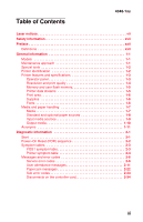
1-7 Standard and optional paper sources 1-8 Input media sources 1-9 Output media 1-10 Acronyms 1-11 Diagnostic information 2-1 Start 2-1 Power-On Reset (POR) sequence 2-2 Symptom tables 2-3 POST symptom table 2-3 Printer symptom table 2-4 Messages and error codes 2-6 Service error codes - Lexmark T430 | Service Manual - Page 4
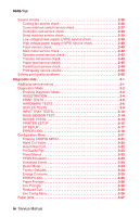
3-22 Reset Maint Cnt 3-22 Prt Quality Pgs 3-23 Panel Menus 3-23 PPDS Emulation 3-23 Download Emuls 3-24 Demo Mode 3-24 Factory Defaults 3-24 Energy Conserve 3-25 ERROR LOG 3-25 Paper Prompts 3-26 Env Prompts 3-26 Reduced Curl 3-26 Exit Config Menu 3-26 Paper jams 3-27 iv Service Manual - Lexmark T430 | Service Manual - Page 5
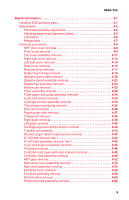
Fuser paper exit guide assembly removal 4-29 Fuser exit sensor removal 4-33 Cartridge contact assembly removal 4-34 Tray damper and spring removal 4-35 Door latch removal 4-36 Paper guide roller removal 4-37 Charge roll removal 4-38 Right guide removal 4-39 Left guide removal 4-40 Cartridge - Lexmark T430 | Service Manual - Page 6
6-1 Scheduled maintenance 6-2 Maintenance kits 6-2 Maintenance kit parts group 6-3 Parts catalog 7-1 How to use this parts catalog 7-1 Assembly 1: Covers 7-2 Assembly 2: Paper feed 7-4 Assembly 3: Frame 7-6 Assembly 4: Multipurpose feeder (MPF 7-8 Assembly 5: Fuser 7-9 Assembly 6: Charging - Lexmark T430 | Service Manual - Page 7
Laser notices 4048-1xx The following laser notice labels may be affixed to this printer as shown: Laser advisory label Laser notices vii - Lexmark T430 | Service Manual - Page 8
in the wavelength region of 770-795 nanometers. The laser system and printer are designed so there is never any human access to laser radiation above a Class I level during normal operation, user maintenance, or prescribed service condition. Laser Der Drucker erfüllt gemäß amtlicher Bestätigung der - Lexmark T430 | Service Manual - Page 9
classe IIIb (3b) all'arseniuro di gallio della potenza di 5mW che opera sulla lunghezza d'onda compresa tra 770 e 795 nanometri. Il sistema laser e la stampante sono stati progettati in modo tale che le persone a contatto con la stampante, durante il normale funzionamento, le operazioni di servizio - Lexmark T430 | Service Manual - Page 10
e 795 nanómetros. O sistema e a impressora laser foram concebidos de forma a nunca existir qualquer possiblidade de acesso humano a radiação laser superior a um nível de Classe I durante a operação normal, a manutenção feita pelo utilizador ou condições de assistência prescritas. x Service Manual - Lexmark T430 | Service Manual - Page 11
Subchapter J, voor andere landen in IEC 60825-1. Laserprodukten van klasse I worden niet als ongevaarlijk aangemerkt. De printer is voorzien van een laser van klasse IIIb (3b), dat wil zeggen een gallium arsenide-laser van 5 milliwatt met een golflengte van 770-795 nanometer. Het lasergedeelte en de - Lexmark T430 | Service Manual - Page 12
kraven i IEC 60825-1. Laserprodukter i Klass I anses ej hälsovådliga. Skrivaren har en inbyggd laser av Klass IIIb (3b) som består av en laserenhet av gallium-arsenid på 5 milliwatt som arbetar användning, underhåll som utförs av användaren eller annan föreskriven serviceåtgärd. xii Service Manual - Lexmark T430 | Service Manual - Page 13
å betrakte som farlige. Skriveren inneholder internt en klasse IIIb (3b)-laser, som består av en gallium-arsenlaserenhet som avgir stråling i serviceoperasjoner. Avís sobre el Làser Segons ha estat certificat als Estats Units, aquesta impressora compleix els requisits de DHHS 21 CFR, apartat J, pels - Lexmark T430 | Service Manual - Page 14
4048-1xx Japanese Laser Notice Chinese Laser Notice xiv Service Manual - Lexmark T430 | Service Manual - Page 15
Korean Laser Notice 4048-1xx Laser notices xv - Lexmark T430 | Service Manual - Page 16
4048-1xx xvi Service Manual - Lexmark T430 | Service Manual - Page 17
is based on testing and approvals of the original design and specific components. The manufacturer is not responsible for safety in the event of use of unauthorized replacement parts. • The maintenance information for this product has been prepared for use by a professional service person - Lexmark T430 | Service Manual - Page 18
des Geräts, bzw. arbeiten Sie mit großer Vorsicht, wenn das Produkt für die Ausführung der Arbeiten an den Strom angeschlossen sein muß. xviii Service Manual - Lexmark T430 | Service Manual - Page 19
personal cualificado debe ser consciente de este peligro y tomar las precauciones necesarias. • PRECAUCIÓN: este símbolo indica que el voltaje de la parte del equipo con la que está trabajando es peligroso. Antes de empezar, desenchufe el equipo o tenga cuidado si, para trabajar con él, debe - Lexmark T430 | Service Manual - Page 20
producte. El personal professional ha d'estar-ne assabentat i prendre les mesures convenients. • PRECAUCIÓ: aquest símbol indica que el voltatge de la part de l'equip amb la qual esteu treballant és perillós. Abans de començar, desendolleu l'equip o extremeu les precaucions si, per treballar - Lexmark T430 | Service Manual - Page 21
4048-1xx Safety information xxi - Lexmark T430 | Service Manual - Page 22
, symptom tables, and service checks used to isolate failing field replaceable units (FRUs). 3. Diagnostic aids contains tests and checks used to locate or repeat symptoms of printer problems. 4. Repair information provides instructions for making printer adjustments and removing and installing FRUs - Lexmark T430 | Service Manual - Page 23
of the factory shipped configuration. Maintenance approach The diagnostic information leads you to the correct field replaceable unit (FRU) or part. Use the error code charts, symptom index, and service checks to determine the symptom and repair the failure. See "Diagnostic information" on page - Lexmark T430 | Service Manual - Page 24
) Slotted screwdriver Small Phillips screwdriver Spring hook When taking voltage readings, always use the printer frame as ground unless another ground is specified. Printer identification Serial number Look for the serial number label on the inside front cover of the printer. 1-2 Service Manual - Lexmark T430 | Service Manual - Page 25
4048-1xx Printer features and specifications Operator panel The operator panel consists of a two-line display and six buttons (Menu is two buttons). General information 1-3 - Lexmark T430 | Service Manual - Page 26
resolution: • 300 dpi ✓ • 600 dpi ✓ • 1200 Image Quality ✓ • 2400 Image Quality ✓ • 1200 dpi ✓ Image Enhancement Technology (IET): • 2 bits/pel ✓ • 4 bits/pel ✓ Toner saver ✓ Print darkness ✓ PictureGrade ✓ ✓ Indicates print quality setting is supported. 1-4 Service Manual - Lexmark T430 | Service Manual - Page 27
Standard memory Standard flash memory Memory options 8MB DIMM 16MB DIMM 32MB DIMM 64MB DIMM 128MB DIMM 256MB DIMM Maximum # of memory DIMM Maximum possible memory Flash memory options 16MB 32MB Maximum # of flash memory options Maximum possible flash memory ✓ Indicates option is supported. Printer - Lexmark T430 | Service Manual - Page 28
Approximate coverage 5% 5% 5% 5% Fonts Fonts/options PCL bitmapped PCL scalable PostScript scalable PPDS bitmapped PPDS scalable All models 2 89 91 5 39 Note: Additional fonts can be downloaded to the printer RAM, or optional user flash. 1-6 Service Manual - Lexmark T430 | Service Manual - Page 29
media, media weights and media textures which together provide optimal print quality across a variety of media. Media supported Paper Card stock Transparency Labels Envelope Bond Media weights Heavy Normal Light Media textures Rough Normal Smooth All models ✓ ✓ ✓ ✓ ✓ ✓ Note: ✓ Indicates - Lexmark T430 | Service Manual - Page 30
Standard and optional paper sources Media sources Standard Standard input sources: • Integrated 250-sheet tray The 250-sheet drawer supports the following sizes: A4, A5, JIS B5, folio, letter, legal, executive, and statement. • Multipurpose feeder Standard output destination (150-sheet sensing bin - Lexmark T430 | Service Manual - Page 31
Input media sources 4048-1xx Integrated 250-sheet tray Multipurpose feeder Optional 250-sheet drawer Optional 500-sheet drawer Duplex (models 101, 102 only) Supported input sizes* Letter ✓ ✓ 11 x 17 Legal ✓ ✓ A4 ✓ ✓ A3 A5 ✓ ✓ Folio ✓ ✓ Statement ✓ ✓ JIS-B4 JIS-B5 ✓ ✓ - Lexmark T430 | Service Manual - Page 32
4048-1xx Output media Supported output sizes 150-sheet standard bin Letter ✓ A4 ✓ Legal ✓ 11 x 17 A3 Folio ✓ Statement ✓ A5 ✓ envelope ✓ B5 envelope ✓ Other envelope ✓ * Size supported, but results may be unacceptable. 20-sheet rear exit ✓ ✓ * ✓ ✓ ✓ 1-10 Service Manual - Lexmark T430 | Service Manual - Page 33
Replaceable Unit Ground High Voltage Power Supply Image Enhancement Technology Kilobyte Liquid Crystal Display Laser Scanning Unit Low Voltage Power Supply Multipurpose Feeder Not And (Gate) Nonvolatile Random Access Memory Personal Identification Number Printer Job Language Power-On Reset Power - Lexmark T430 | Service Manual - Page 34
4048-1xx 1-12 Service Manual - Lexmark T430 | Service Manual - Page 35
the "Symptom tables" on page 2-3. • If you have an error message or user message, check the following: - "Service error codes" on page 2-6 - "User attendance messages" on page 2-11. • Additional information: - "Service checks" on page 2-36 - "Solving print quality problems" on page 2-56. Diagnostic - Lexmark T430 | Service Manual - Page 36
. 6. Close Door will be posted if the cover is open. 7. Any cartridge errors, such as Defective Cartridge are posted. 8. Applicable maintenance messages are posted. For example, 80 Scheduled Maintenance. 9. Applicable toner low messages are posted. 10. The printer displays Ready. 2-2 Service Manual - Lexmark T430 | Service Manual - Page 37
tables POST symptom table These symptoms may appear during the POST (Power-on Self Test). See "Power-On Reset (POR) sequence" on page 2-2 for the sequence when a printer is turned on. Symptom The main motor, cooling fan and fuser do not come on. POST completes except display is incomplete or - Lexmark T430 | Service Manual - Page 38
4048-1xx Printer symptom table Symptom Dead machine (no power) Fan noisy or not working Fuser parts melted Fuser heater does not activate Toner not fused to the paper Blank page Black page Heavy background Light print White or black lines or bands Toner on back of page Paper jams Main motor noisy or - Lexmark T430 | Service Manual - Page 39
4048-1xx Symptom Printer not communicating with host Paper wrinkled or bent Top cover will not close Operator panel button does not respond Operator panel light does not light or is very dim Action See "Parallel port service check" on page 2-49. See "Paper "trees," wrinkles, stacks poorly or curls - Lexmark T430 | Service Manual - Page 40
of support. An unrecoverable system software error. Reset the printer (POR). If the problem continues, replace the controller card. The load on the exit motor is too high or there is a cabling problem. First, check for jams and then move the exit rollers, located between the rear door and fuser - Lexmark T430 | Service Manual - Page 41
4048-1xx Service error codes (9xx) (continued) Error Description Action 923 Fuser error Fuser is too hot during printing or when printer is idle. Go to "Fuser service check" on page 2-40. 924 Fuser error An open circuit has been detected in the fuser thermistor circuit. Check cabling and - Lexmark T430 | Service Manual - Page 42
been installed. • If all the above are correct, replace the LVPS assembly. This error indicates an open fuse in line to tray 2. POR the printer to reset the fuse. Check for +24 V dc on J21, pin 6. If correct, the fuse is okay. If incorrect, remove the drawer and check resistance between pin 6 and - Lexmark T430 | Service Manual - Page 43
(POR). If this does not fix the problem, replace the controller card. Before proceeding, perform a power on reset (POR) to see if the ECC error correction code can reflash NAND. If this does not fix the problem, replace the controller card. Error codes 956, 957, and 959 are controller card failures - Lexmark T430 | Service Manual - Page 44
the downloaded emulations. If the problem persists, replace the emulation card. 975 Unrecognizable network port 976 Software error in network port A failure with the network port. If the printer is a network model, replace the controller card. See "Controller card assembly removal" on page 4-50 - Lexmark T430 | Service Manual - Page 45
Change Remove the print cartridge and install a new cartridge. This message displays when the user should change the media installed in one of the input options. • =Tray 1, Tray 2, Tray 3, or MP feeder. • =Custom 1 through Custom - Lexmark T430 | Service Manual - Page 46
other Envelope. Tray x=Tray 2 or Tray 3. This messages displays for the following conditions: • The specified device may have been removed from the printer, possibly to clear a paper jam or to uninstall the option. • The option may be attached to the printer, but a communications problem may prevent - Lexmark T430 | Service Manual - Page 47
The printer does not detect the presence or absence of a tray, but that paper was not picked. Replace the tray and press Go. Note: This situation usually occurs when the tray is refilled during a job. To refill a tray during a printing session, press Stop and wait for pages to reach the output bin - Lexmark T430 | Service Manual - Page 48
of the following: - Cancel Job - Reset Printer If the message cannot be cleared, go to "Input tray(s) service check" on page 2-64. Input source=Tray 1, Tray 2, Tray 3, or MP Feeder. Size=Letter, Legal, B5, A4, A5, Exec, Univ., Folio, or Stmt. The following actions may be taken: • Load media in the - Lexmark T430 | Service Manual - Page 49
: • Load media in the indicated source. • Press Menu until Busy/Waiting displays. Select one of the following: - Cancel Job - Reset Printer If the message cannot be cleared, go to "Input tray(s) service check" on page 2-64. When a PIN (personal identification number) is added to a Confidential Print - Lexmark T430 | Service Manual - Page 50
. If pages are allowed to print, then they are not reprinted once a good print cartridge is inserted. Replace the cartridge. The printer determines the paper length is too short to print the formatted data. This occurs when the printer does not know the actual paper size loaded in the tray. Make - Lexmark T430 | Service Manual - Page 51
. Note: This message is posted prior to the actual start of the defragment operation. The printer code determines if enough printer memory is available to complete the defragment operation. The user should not be concerned with losing resources stored in the flash option. The following actions may - Lexmark T430 | Service Manual - Page 52
be available: - Cancel Job - Reset Printer This message displays when the page is too complex to print. The following actions may be print job and reprint, if necessary. • Press Menu until Busy/Waiting appears. The following selections are possible: - Cancel Job - Reset Printer 2-18 Service Manual - Lexmark T430 | Service Manual - Page 53
containing unsupported code is detected. Press and hold Go while powering the printer. The unsupported card will be ignored. Remove the card. This message displays when the PPDS interpreter has encountered a font error. Note: This error may only occur when the printer is formatting PPDS print data - Lexmark T430 | Service Manual - Page 54
may be taken: • Press Go to clear the message. The printer discards any data received on the USB port. • Press Menu until Busy/Waiting appears and select Reset Printer. This error code displays when too many input trays are attached to the printer. Remove the extra trays. 2-20 Service Manual - Lexmark T430 | Service Manual - Page 55
option. Replace the fuser assembly, transfer roller, charge roll, and pick rolls at this recommended interval to maintain the print quality and reliability of the printer. The parts are available as a maintenance kit. For more information, see "Scheduled maintenance" on page 6-2. This error displays - Lexmark T430 | Service Manual - Page 56
adjusted reference guide. • Debris in the paper path. • Paper not of the specified length. Paper jam messages Message 200 Paper Jam Remove Cartridge 201 Paper Jam Remove Cartridge 202 Paper Jam Open Rear Door 231 Paper Jam Remove Tray1 Pull Down Lever At Printer Rear 235 Paper Jam Remove Tray1 Pull - Lexmark T430 | Service Manual - Page 57
238 Paper Jam Check Duplex 239 Paper Jam Remove Tray 1 Pull Down Lever At Printer 242 Paper Jam Check Tray 2 243 Paper Jam Check Tray 3 250 Paper Jam Check MP Feeder 1565 Emul Error Load Emul Option Explanation A piece of media is most likely jammed in the duplex area. Remove tray 1 and - Lexmark T430 | Service Manual - Page 58
to help isolate paper jams and paper feed problems in the base printer. DU xx DU xx xx xx xx xx xx xx To identify the bytes: Byte 1 Byte 2 Byte 3 Byte 4 DU xx xx xx xx DU xx xx xx xx Byte 5 Byte 6 Byte 7 Byte 8 Displayed error codes When a 9xx or 2xx error displays: 1. Press - Lexmark T430 | Service Manual - Page 59
-1xx Values In the table below, the values for common variables are listed below: • media source 10=Multipurpose tray (MPT) 11=Tray 1 12=Tray 2 13=Tray 3 80=Duplex unit • media size 1=Letter 2=Legal 3=B5 4=A4 5=Executive 6=A5 7=Custom size 9=7¾ in. envelope A=#9 Envelope B=#10 Envelope C=8.661 in - Lexmark T430 | Service Manual - Page 60
Possible error message This code indicates printer input sensor and flag for correct operation. The flag should operate freely. • Check for debris in the area of the input sensor. • Check the area of the transfer roll and input to the fuser for anything that might cause the paper Service Manual - Lexmark T430 | Service Manual - Page 61
-1xx Sub error codes (continued) First 6 bytes sub error code data (xx can be any value) 84 xx 04 84 xx 05 x1 84 xx 0F x1 x2 x3 84 xx 18 Explanation Possible error message The input sensor was covered (activated) during POST. • Clear the media or debris from the printer. • Run the base sensor - Lexmark T430 | Service Manual - Page 62
expected 200 page. (x1=media size, x2=media source) Check the pass thru sensor to make sure it is operating properly. If no problem is found, it may still be necessary to try a new pass thru sensor. This code indicates that the media 200 activated the input sensor before the printer EP - Lexmark T430 | Service Manual - Page 63
Diagnostic Mode" on page 3-2 and "BASE SENSOR TEST" on page 3-14. Paper at input sensor when not expected 200 during printing. Possible cause is multiple sheets picked. The main motor driver failed to detect a 200 specific motor after two tries. Possible causes for this error are: • The main - Lexmark T430 | Service Manual - Page 64
or redrive assembly. Feed a sheet of paper, and if the same error occurs after clearing the fuser or the same error occurs when no media is present, check the exit sensor assembly. Turn the printer off, enter the diagnostic tests menu, and select the base sensor test. Select output sensor and check - Lexmark T430 | Service Manual - Page 65
never activated 201 by the leading edge of the media fed through the printer. • This error can be displayed after a 201 paper jam. • This can be caused by a defective fuser exit sensor assembly. Note: Enter the diagnostic tests menu, select Base Sensor Tests, select Output Sensor Test and check the - Lexmark T430 | Service Manual - Page 66
4048-1xx Sub error codes (continued) First 6 bytes sub error code data (xx Page detected over tray pass thru at 200 warm-up and tried to feed out, but did not reach the input sensor in time. Duplex sensor was never made by 231 leading edge of page. (x1+x2=timeout value) 2-32 Service Manual - Lexmark T430 | Service Manual - Page 67
4048-1xx Sub error codes (continued) First 6 bytes sub error code data (xx can be any value) 8F xx 01 00 00 00 8F xx 02 x1 x2 00 Explanation Possible error message Duplex sensor covered, paper not 238 expected (paper in duplex during warm- up. Duplex sensor never changed state when 235 - Lexmark T430 | Service Manual - Page 68
940 Close Door Load MP Feeder POST POST POST Print multiple pages POST POST POST POST POST Pick paper from MPF Check connection at: Connector name and description J17 LVPS (low voltage power supply) J5 OP-PANEL (operator panel) Go to "Dead machine service check" on page 2-39 (second - Lexmark T430 | Service Manual - Page 69
if cable is unplugged Load Tray 1 Paper Jam Remove Paper Standard Bin Option tray is not available Condition required to obtain error Pick paper from tray1 Print a page from any source POST Attempt to select option tray in PAPER SOURCE menu Check connection at: Connector name and description - Lexmark T430 | Service Manual - Page 70
replace the fan. • If voltage is not present, disconnect the cable from the controller card (J19) and check for continuity on each cable. - If the cable is good, see "Controller card service check" on page 2-38 for more information. - If the cable is damaged, replace the cable. 2-36 Service Manual - Lexmark T430 | Service Manual - Page 71
4048-1xx Cover interlock switch service check Note: Make sure a print cartridge is installed and the cover closes all the way, fully engaging spade of the cable. • If voltage is not present, see "Controller card service check" on page 2-38. Replace the switch if faulty. Diagnostic information 2-37 - Lexmark T430 | Service Manual - Page 72
of the printhead. Note: U.S. versus non-U.S. and the printer configuration ID can be reset. This affects default measurements and paper size. This can be changed. See "Defaults" on page 3-15 in the Diagnostics Mode. See "Diagnostics Mode" on page 3-2 for more information. 2-38 Service Manual - Lexmark T430 | Service Manual - Page 73
the nominal-220 V model printer Low voltage power supply (LVPS) service check FRU Low voltage power supply (LVPS) (100 V, 110 V, or 220 V) Action Unplug the power cord and verify that the cable is correct and functioning. Replace if necessary. With the power cord unplugged, remove the HVPS fan and - Lexmark T430 | Service Manual - Page 74
, remove the HVPS and check the cartridge contact assemblies (springs) for continuity and damage. If the charge roll and the cable at C show discontinuity, replace the left guide assembly. See "High voltage power supply (HVPS)" on page 5-8 for testing the board. Fuser service check When toner is - Lexmark T430 | Service Manual - Page 75
(pins #1 and #3 or outer pins). If there is no continuity, replace the fuser assembly. See "Fuser assembly removal" on page 4-26. If there is continuity, follow these steps: 1. Reconnect the fuser heater cable. 2. Replug and turn the printer on. Measure the voltage between the connectors on the back - Lexmark T430 | Service Manual - Page 76
. - If voltage is correct, replace the controller card. - If the voltage is not correct, check the LVPS. Note: Always check printhead alignment after replacing the controller card assembly. See "Printhead assembly adjustment" on page 4-2 for hardware alignment of the printhead. 2-42 Service Manual - Lexmark T430 | Service Manual - Page 77
proper operation. See"Power-On Reset (POR) sequence" on page 2-2. FRU Operator panel Operator panel cable Controller card assembly Action If the buttons do not depress or click when pressed, replace the operator panel. If the operator panel does not illuminate, turn the printer off and unplug J5 - Lexmark T430 | Service Manual - Page 78
damage or lack of proper function. Inspect the transfer roll for signs of wear, damage, or contamination. Replace the assembly as necessary. Note: Do not vacuum the roll. Note: Always check the bottom margin following a transfer roll replacement. See "REGISTRATION" on page 3-4 2-44 Service Manual - Lexmark T430 | Service Manual - Page 79
Paper feed service checks Paper picks and advances approximately four inches 4048-1xx FRU Reference feed assembly Backup roller assembly Paper feed gear Drive assembly Action Turn printer off and remove the print cartridge and left side cover. With a left finger, rotate the main motor - Lexmark T430 | Service Manual - Page 80
jam error indication during POST FRU Stack control flags Photo sensor Photo sensors (paper path) Action If the exit sensor flag is not resting within the paper exit sensor during POST, the printer indicates Remove Paper/Standard Bin. Make sure the flag is operating freely and correctly. Replace - Lexmark T430 | Service Manual - Page 81
+5 V dc on pins #1, #4, #7, and ground on pins #3, #6, and #9. See "Locations and connections" on page 5-1 for more information. • If correct, replace the input paper feed sensor. • If the voltage is not correct, replace the controller card assembly. Note: Always check printhead alignment after - Lexmark T430 | Service Manual - Page 82
the shaft to be released without the solenoid being activated. Replace the paper feed assembly as necessary. Note: We recommend that the paper feed roll be replaced when the paper feed assembly is replaced. Also see "Paper picks during POST and/or continuously" on page 2-46. 2-48 Service Manual - Lexmark T430 | Service Manual - Page 83
backup roller causes the printer to run hotter than required for the media being printed. Excessive heat can cause paper treeing problems, poor stacking, or excessive curl. Parallel port service check 1. Perform a print test to make sure the printer prints correctly. See "Prt Quality Pgs" on page - Lexmark T430 | Service Manual - Page 84
cartridge removed and the printer off, check continuity between HVPS (DC designation on outer side of card) and the PC pin inside the printer. The PC pin is directly above the transfer roll gear. Replace the cartridge contacts as necessary. See "High voltage power supply (HVPS)" on page 5-8. Verify - Lexmark T430 | Service Manual - Page 85
continuity fails, replace the left guide assembly which includes this cable. Check continuity from the charge roll left side bushing to the right side shaft. If continuity fails, remove the charge roll and clean the left side shaft and bushing. See "High voltage power supply (HVPS)" on page 5-8 and - Lexmark T430 | Service Manual - Page 86
to evenly distribute the toner. If the print cartridge is low, try a new one. Check springs at each end of the fuser backup roller to ensure adequate and even pressure is applied to the fuser belt. Replace the fuser if necessary. Make sure recommended paper is being used. 2-52 Service Manual - Lexmark T430 | Service Manual - Page 87
check the spring of the guide assembly. Replace the faulty guide assembly (either right or left). If force seems similar, try a new cartridge. Check the springs and bearings at both ends of the transfer roller. The bearing assemblies should support the transfer roller, applying even pressure to the - Lexmark T430 | Service Manual - Page 88
at a time in the order shown: • Transfer roller Note: Always check the bottom margin following a transfer roll replacement. See "REGISTRATION" on page 3-4 • Cartridge contact assembly • HVPS card White or black lines or bands FRU Print cartridge Paper feed drive gears Action Banding appears as - Lexmark T430 | Service Manual - Page 89
back of the paper. Inspect the belt and backup roller for signs of contamination, and replace fuser assembly as necessary. A transfer roller contaminated with toner can cause toner to transfer to the back of printed pages. Inspect the transfer roller for contamination and replace as necessary. Note - Lexmark T430 | Service Manual - Page 90
is printing on transparencies, card stock, or labels, be sure to check the Paper Type in the printer driver or operator panel. If the media has an uneven surface, adjust the driver or printer Paper Weight and Paper Texture. • The print cartridge may be defective. Replace it. 2-56 Service Manual - Lexmark T430 | Service Manual - Page 91
or back of the page. Action • Make sure the paper is straight and unwrinkled. • Check for loose toner in the printer. • Clean the printer. • If the problem persists, replace the cartridge. Vertical or horizontal streaks appear on the page. • Replace the print cartridge. Marks repeating Measure - Lexmark T430 | Service Manual - Page 92
the printer driver. • Change the media texture setting. You can download the latest driver from the Lexmark Web site, www.lexmark.com. The print is getting light but Toner Low does not display. The Toner Low message appears. Solid black areas on transparencies or paper contains white streaks. Pages - Lexmark T430 | Service Manual - Page 93
the media types and sizes chart in the User's Reference). • Remove the paper from tray 1 and fan the paper. • Make sure tray 1 is selected from the printer driver. • Do not overfill the tray. • Make sure the printer recognizes the optional trays. POR the printer and check the cables. • Make sure the - Lexmark T430 | Service Manual - Page 94
4048-1xx Problem The Load Paper displays even though there is paper loaded in the optional tray 2 or tray 3. The printer does not print after a paper jam has been cleared. Unexpected characters print or characters are missing. Action • Make sure the tray is pushed all the way in. • Press Go. • - Lexmark T430 | Service Manual - Page 95
procedures to identify printer failures and verify repairs have corrected the problem. Additional service menus Several service menus are available a user. Generally, the options made available in this menu group are used to configure a printer for operation. See "Configuration Menu" on page 3-21 - Lexmark T430 | Service Manual - Page 96
MP Feeder Prt Quality Pages HARDWARE TESTS LCD Test Button Test DRAM Test Parallel Wrap (displays in some configurations) DUPLEX TESTS Quick Test Top Margin Sensor Test Duplex Feed 1 INPUT TRAY TESTS Feed Test Sensor Test BASE SENSOR TEST Toner Input Output Narrow Media Front Door 3-2 Service Manual - Lexmark T430 | Service Manual - Page 97
PRINTER SETUP Defaults Page Count Perm Page Count Serial Number Engine Setting 1 Engine Setting 2 Engine Setting 3 Engine Setting 4 Model Name Configuration ID Edge to Edge Par S Strobe Adj EP SETUP EP Defaults Fuser Temp Transfer Print Contrast Charge Roll Gap Adjust ERROR LOG Display Log Print - Lexmark T430 | Service Manual - Page 98
again. 4. To exit, press Return. 5. Test the setting by printing the Quick Test page for all the source, see "PRINT TESTS" on page 3-5. Select all the available sources. To test the Duplex sources, see "DUPLEX TESTS" on page 3-9 Print the Quick Test Page on letter or A4 paper. 3-4 Service Manual - Lexmark T430 | Service Manual - Page 99
PRINT TESTS from Diagnostics Mode. 2. Select the input source from the sources displayed on the Feed Test menu. All installed sources are listed. Menu selections Tray 1 Tray 2* Tray 3* MP Feeder * If installed Description Standard tray Optional tray Optional tray Multipurpose feeder 3. Select - Lexmark T430 | Service Manual - Page 100
print the Print Quality pages: 1. Select PRINT TESTS from Diagnostics Mode. 2. Select Prt Quality Pgs. 3. Press Select. Four pages print. Additional button presses are ignored until the pages have printed. If duplex is selected, the pages print Return or Stop to cancel the test. 3-6 Service Manual - Lexmark T430 | Service Manual - Page 101
the validity of DRAM, both standard and optional. The test writes patterns of data to SDRAM to verify that each bit in memory can be set and the test stops, the power indicator is turned on solid, and the final results display. If the test fails, the message DRAM Error, displays for approximately - Lexmark T430 | Service Manual - Page 102
2 Wrap, or Parallel 3 Wrap. The power indicator blinks indicating the test is in progress. Error Byte Interrupt Request Error Strobe Interrupt Request Error Init Fail Error Init Busy Error Host Busy Error RAM Data FF Error RAM Data AA Error RAM Data 00 Error RAM Data 55 Error 3-8 Service Manual - Lexmark T430 | Service Manual - Page 103
a duplex sheet to the front, make sure you adjust the Top Margin for a single sheet. See "REGISTRATION" on page 3-4. Use either letter or A4 paper to run the test. Quick Test Printing... If wider or narrower paper is used, media width appears with either W for wide or N for narrow - Lexmark T430 | Service Manual - Page 104
until Return or Stop is pressed. The printer attempts to print the Quick Test Page from the default paper source. If the default paper source only supports envelopes, then the page is printed from Tray 1. 4. Check the Quick Test Page for the correct offset between the placement of the first scan - Lexmark T430 | Service Manual - Page 105
Duplex Tests menu. 2. Manually actuate each of the duplex power indicator blinks while the paper is feeding. Duplex Feed 1 Feeding... 2. When the paper reaches the duplex paper stop position 1, the power indicator turns on solid and a message appears: Duplex Feed 1 Clear Paper... 3. Remove the paper - Lexmark T430 | Service Manual - Page 106
Test This test is used to determine if the input tray sensors are working correctly. 1. Select the Sensor Test from the Input Tray Test menu. 2. Select the input source. Only installed sources display, but may include Tray 1, Tray 2, Tray 3, MP Feeder. Testing... 3-12 Service Manual - Lexmark T430 | Service Manual - Page 107
indicates which sources should display which sensors. Source Tray present (TP) Tray 1 Tray 2 Yes1 Yes2 Tray 3 No Multipurpose feeder Yes 1 Only available when tray 2 is installed. 2 Only available when tray 3 is installed 3 Only available if tray is 250-sheet drawer. Pass thru sensor (P) No - Lexmark T430 | Service Manual - Page 108
is used to determine if the sensors inside the printer are working correctly. To run the Base Sensor Test: 1. Select BASE SENSOR TEST from the Diagnostics Mode. 2. Select the sensor to test. The following sensors may be tested: Toner (toner optical sensor) Input (input sensor) Output (exit sensor - Lexmark T430 | Service Manual - Page 109
Envelope Fax paper size Letter A4 PCL Symbol Set PC-8 PC-850 PPDS code page 437 850 Units of measure Inches Millimeters * Where input sources do not have size sensing capabilities. Warning: Changing the Defaults setting causes the printer to reset the printer NVRAM to factory settings - Lexmark T430 | Service Manual - Page 110
4048-1xx Page Count Reset the page count when an engine card is replaced. To reset the page count: 1. Select Page Count from the PRINTER SETUP menu. Page Count =1234567* 2. The leftmost number blinks. Use Menu . A value of zero indicates no change is made from the factory setting. 3-16 Service Manual - Lexmark T430 | Service Manual - Page 111
), and High. Charge Roll Selections are Low, Medium (default), and High. Gap Adjust Adjusts the minimum gap between sheets during printing. This setting reduces speed (pages per minute), but can be used to reduce curl of printed media and improve stacking in the output bin. Range is 0 (default - Lexmark T430 | Service Manual - Page 112
screen, press Menu. For example: 1-200 3-928 2-920 4-922 5-250 7-230 6-990 8-230 9-953 11-000 10-000 12-000 In this example, the last error was a 200 error. In positions 10, 11, and 12, no codes were recorded. 2. Press Return to exit the error log. 3-18 Service Manual - Lexmark T430 | Service Manual - Page 113
number. • Time and date stamps • Page counts for each error. Model and Serial number Printer information Page count Panel display when error occurred Sub error codes Next error code The printed error log can be faxed to Lexmark or your next level of support for verification or diagnosis. This report - Lexmark T430 | Service Manual - Page 114
4048-1xx Clear Log 1. Select Clear Log from the Error Log menu. Clear Log =Yes 2. Press Yes to confirm. Select No to exit without clearing the log. 1-000 3-000 2-000 the log. Exit Diagnostics Select Exit Diagnostics to exit the Diagnostic Mode and return to normal mode. 3-20 Service Manual - Lexmark T430 | Service Manual - Page 115
. The menu items appear on the operator panel in the order shown: Maint Cnt Value Reset Maint Cnt Prt Quality Pgs Panel Menus PPDS Emulation Download Emuls Demo Mode Factory Defaults Energy Conserve ERROR LOG Paper Prompts Env Prompts Reduced Curl Exit Config Menu Select Exit Config Menu to exit the - Lexmark T430 | Service Manual - Page 116
appears and the maintenance kit is installed (see "Scheduled maintenance" on page 6-2), this number should be reset. To reset the counter: 1. Select Reset Maint Cnt from the CONFIG MENU. Reset Maint Cnt =Reset 2. Press Select to reset the counter to zero. Press Return to cancel. 3-22 Service Manual - Lexmark T430 | Service Manual - Page 117
4048-1xx Prt Quality Pgs To print the Print Quality Pages: 1. Select Prt Quality Pgs from CONFIG MENU. 2. Press Select. Four pages print. Additional button presses are ignored until the pages have printed. If duplex is selected, the pages print front and back. The first page is a mix of graphics and - Lexmark T430 | Service Manual - Page 118
Defaults This menu lets you restore the printer settings to their factory default values. 1. Select Factory Defaults from the Configuration Menu. 2. Select either Restore Base or Restore Network. Restore Network is only available if an integrated network adapter is installed. 3-24 Service Manual - Lexmark T430 | Service Manual - Page 119
you select Off, an additional item appears in the Power Saver menu. Disable lets you enable or disable Power Saver from the customer menu. ERROR LOG See "ERROR LOG" on page 3-18 for a more detailed description. The error log printed from the Diagnostics Mode contains additional debug information for - Lexmark T430 | Service Manual - Page 120
To print the error log: 1. Select Print Log from the Error Log menu. 2. Press Return to exit the Error Log menu. Paper Prompts Setting Paper Prompts controls which tray a change prompt is directed to when paper is sensed to be the wrong size. Selections include Auto, MP Feeder, and Manual Paper. Env - Lexmark T430 | Service Manual - Page 121
loading of the media. Note: To clear the Paper Jam error message, you must remove all jammed print media from the entire paper path. The following illustration shows the path that print media travels through the printer. The path varies depending on the input source (trays and multipurpose feeder - Lexmark T430 | Service Manual - Page 122
4048-1xx 3-28 Service Manual - Lexmark T430 | Service Manual - Page 123
ESD-sensitive parts, follow the instructions below in addition to all the usual precautions, such as turning off power before removing logic cards: • Keep the ESD-sensitive part in its original shipping container (a special "ESD bag") until you are ready to install the part into the printer. • Make - Lexmark T430 | Service Manual - Page 124
Skew Printhead misalignment To align the printhead: 1. Enter the Diagnostic Menu. See "Entering Diagnostic Mode" on page 3-2 and print the Quick Test. To print the test: a. Select Print Tests from the Diagnostic Menu. b. Select Tray 1. c. Select Single. The Quick Test prints. 4-2 Service Manual - Lexmark T430 | Service Manual - Page 125
2. Fold the printed test page on the left side so that a few millimeters of grid lines wrap around the outside of the fold. 3. Fold a second vertical fold near the center so that the left side top edge aligns with the right side top edge. 4. If the grid lines of the paper on the - Lexmark T430 | Service Manual - Page 126
margins. See "REGISTRATION" on page 3-4. Note: Printhead misalignment results in skewed horizontal lines but a consistent margin top to bottom of page. Paper feed misalignment results in entire image rotated on the paper. See "Adjusting paper feed alignment (skew)" on page 4-5. 4-4 Service Manual - Lexmark T430 | Service Manual - Page 127
which rotates paper counterclockwise in the printer path (image clockwise) and vice versa. Verify alignment by printing the Quick Test page: 1. Enter the Diagnostic Menu. See "Entering Diagnostic Mode" on page 3-2 2. Select Print Tests from the Diagnostic Menu. 3. Select Tray 1. 4. Select Single - Lexmark T430 | Service Manual - Page 128
must be lubricated when installed. The following diagrams indicate the units requiring lubricant and show where to place it. Place a 23 (P/N 99A0462). Note: Be careful to not spread the grease to other parts of the printer. P/N 56P23637 Ratchet drive Lubricate the teeth of all the gears in the drive - Lexmark T430 | Service Manual - Page 129
assembly P/N 56P2302 Rear cover assembly Reassembly Ensure all cables are reconnected when reassembling the printer. The printer may not detect a disconnected sensor in some areas without extensive running. Note: Always print a page from each paper source to verify reassembly. Repair information 4-7 - Lexmark T430 | Service Manual - Page 130
unplug the power cord whenever you are working on the printer with one of the covers removed. Remove the print cartridge and paper tray before you perform removal procedures. Unless otherwise stated, reinstallations are in reverse order of removal. MPF door cover removal 1. Remove the tray. 2. Open - Lexmark T430 | Service Manual - Page 131
4048-1xx Front cover removal 1. Open the front cover. 2. Remove the two screws holding the front cover to the hinge arm (A). 3. Unlatch the ends of the hinge arms. Repair information 4-9 - Lexmark T430 | Service Manual - Page 132
cable cover and remove the cable cover. 5. Disconnect the operator panel cable (C) from the operator panel. 6. Remove the front cover with the operator panel attached. If replacing the front cover, remove the operator panel. See "Operator panel assembly removal" on page 4-22. 4-10 Service Manual - Lexmark T430 | Service Manual - Page 133
4048-1xx Top cover assembly removal 1. Remove the front cover. See "Front cover removal" on page 4-9. 2. Remove the two screws as shown (A). 3. Remove the E-clips from both hinges that connect the left and right guides to the top cover (B). 4. Remove the stud hinges. 5. Open the rear exit door. 6. - Lexmark T430 | Service Manual - Page 134
the front cover. 3. Open the MPF door. 4. Remove the screw below the front cover which fastens the side cover to the frame (A). 5. Open the rear cover and remove the second screw down from the top left corner (B). 6. Pull the top of the right cover away from the printer slightly. 4-12 Service Manual - Lexmark T430 | Service Manual - Page 135
4048-1xx 7. Unlatch the cover from the frame behind the front of tray (C). 8. Remove the cover. The MPF door may need to be lifted slightly for the side cover to clear. Repair information 4-13 - Lexmark T430 | Service Manual - Page 136
4048-1xx Left side cover removal 1. Open the front cover and the MPF door. 2. Disengage the two latches (A) located in the front and top. 3. Swing the left side cover away from the printer. 4-14 Service Manual - Lexmark T430 | Service Manual - Page 137
4048-1xx Rear cover removal 1. Remove the paper tray. 2. Remove the right side cover. See "Right side cover removal" on page 4-12. 3. Remove the left side cover. See "Left side cover removal" on page 4-14. 4. Disconnect the sensor cable (in-line connector) (A) below the lower left corner of the - Lexmark T430 | Service Manual - Page 138
carefully. Do not touch the rollers. • When reinstalling the rear cover, position the fuser exit guide fingers so they are not bound by the rear cover. A bind causes jams. • Be sure the spring contacts on the left side of the rear cover make good contact with the LVPS cage. 4-16 Service Manual - Lexmark T430 | Service Manual - Page 139
4048-1xx Rear exit door removal 1. Open the rear exit door. 2. Use your index finger or flatblade screwdriver to disengage the left (facing the back of printer) hinge (A) from the rear cover. 3. Swing the left side out to clear the printer and then move the door to the left to disengage the right - Lexmark T430 | Service Manual - Page 140
1. Open the front cover. 2. Remove the two screws (A) holding the front top cover. 3. Remove the two screws (B) from the rear. 4. Lift the rear part of the top cover to clear the output tray full flags. You do not have to disconnect the top cover from the left and right guides. 4-18 Service Manual - Lexmark T430 | Service Manual - Page 141
4048-1xx 5. Press the side of the flag to unclip the flag from the frame. 6. Repeat to remove the other flag. Repair information 4-19 - Lexmark T430 | Service Manual - Page 142
five screws (B), slide the controller card cage cover toward the rear, and remove. 4. Disconnect the cable from the controller card (C). 5. Withdraw the cable through the cage and frame. 6. Remove the screw in the front cover holding the cable cover. 7. Remove the cable cover. 4-20 Service Manual - Lexmark T430 | Service Manual - Page 143
4048-1xx 8. Disconnect the cable from the operator panel card. Repair information 4-21 - Lexmark T430 | Service Manual - Page 144
will be permanently lost. 1. Remove the operator panel cable. See "Operator panel cable removal" on page 4-20. 2. Lift the front cover, unclip the clear bezel from the bottom of the cover, and lift from the bezel from the operator panel. 3. Set aside the language overlay. 4-22 Service Manual - Lexmark T430 | Service Manual - Page 145
4048-1xx 4. Press each of the four tabs (A) while gently prying up the same corner of the operator panel assembly (B) until the panel is free. 5. Remove the operator panel assembly. Repair information 4-23 - Lexmark T430 | Service Manual - Page 146
the printer, if not already removed. 2. Remove the print cartridge. 3. Tilt the printer on its back. 4. Remove the five screws (A) holding the bottom panel. 5. Swing the right side away from the printer and disconnect the paper input sensor cable. 6. Remove the duplex assembly. 4-24 Service Manual - Lexmark T430 | Service Manual - Page 147
4048-1xx Bottom pan removal This removal is for a model (4048-111) without a duplex unit. 1. Disconnect the computer and power cables at the back of the printer, if not already removed. 2. Remove the print cartridge. 3. Tilt the printer onto its back. 4. Remove the five screws (A) holding the bottom - Lexmark T430 | Service Manual - Page 148
4-12. 4. Remove the rear cover. See "Rear cover removal" on page 4-15. 5. Disconnect the thermistor and exit sensor cables (A) at the printer frame to the right of the fuser. 6. Disconnect the fuser from the LVPS (B) on the left side and free the cables from the printer frame. 4-26 Service Manual - Lexmark T430 | Service Manual - Page 149
shank Phillips screwdriver, remove the four screws (C) which fasten the fuser metal frame to the printer frame. 8. Carefully slide the fuser out while pressing the duplex diverter. Non-duplex models do not have the diverter. The front cover door must be closed to remove the fuser. Repair information - Lexmark T430 | Service Manual - Page 150
4048-1xx Installation notes: • During reassembly of the fuser, keep the front door closed to prevent separation of the roller in the fuser. • Be sure to route the cables through the frame and through the cable retainer (D). 4-28 Service Manual - Lexmark T430 | Service Manual - Page 151
Fuser paper exit guide assembly removal 4048-1xx 1. Unplug the printer. 2. Remove the left side cover. See "Left side cover removal" on page 4-14. 3. Remove the right side. See "Right side cover removal" on page 4-12. 4. Remove the rear cover. See "Rear cover removal" on page 4-15. 5. Using a long - Lexmark T430 | Service Manual - Page 152
fuser out far enough to reach the screw that holds the exit guide (B). Remove the screw. Note: Insert the screwdriver through the top cover to access the screw with the minimum fuser movement. If there is a washer between the guide and the fuser, be sure to reinstall the washer. 4-30 Service Manual - Lexmark T430 | Service Manual - Page 153
from the frame. 8. Swing the right side out enough to clear the metal frame. 9. Use the springhook to disconnect the spring on the left. 10. Remove the exit guide assembly. Repair information 4-31 - Lexmark T430 | Service Manual - Page 154
4048-1xx Installation notes: • During reassembly of the fuser exit guide assembly, keep the front door closed to prevent separation of the roller in the fuser. • Be sure to route the cables through the frame and through the cable retainer (C). 4-32 Service Manual - Lexmark T430 | Service Manual - Page 155
4048-1xx Fuser exit sensor removal 1. Remove the fuser paper exit guide. See "Fuser paper exit guide assembly removal" on page 4-29. 2. Use your right index finger to push the tangs (A) of the sensor out of the metal frame. 3. Disconnect the sensor from the cable and remove. Repair information 4-33 - Lexmark T430 | Service Manual - Page 156
assembly removal 1. Remove the HVPS. See "HVPS card removal" on page 4-75. 2. Remove the cartridge contact assemblies (A). A Note: The lower right cartridge contact (to the transfer roll) is a different color from the others. Be sure to reinstall this one in the same location. 4-34 Service Manual - Lexmark T430 | Service Manual - Page 157
4048-1xx Tray damper and spring removal 1. Remove the right side cover. See "Right side cover removal" on page 4-12. 2. Remove the tray damper spring from the printer frame post (A). 3. Rotate the lever counterclockwise as far as possible and lift out. Repair information 4-35 - Lexmark T430 | Service Manual - Page 158
4048-1xx Door latch removal 1. Remove the right side cover. See "Right side cover removal" on page 4-12. 2. Remove the two screws (A). 3. Remove the left side cover. See "Left side cover removal" on page 4-14. 4. Remove the latch on the left side. 4-36 Service Manual - Lexmark T430 | Service Manual - Page 159
-1xx Paper guide roller removal 1. Remove the HVPS. See "HVPS card removal" on page 4-75. 2. Remove the print cartridge. 3. Remove the upper body MPF assembly. See "Upper MPF housing assembly (with paper flag) removal" on page 4-66. 4. Unsnap the latch, which is part of the roller hub (A). 5. Remove - Lexmark T430 | Service Manual - Page 160
4048-1xx Charge roll removal Warning: Handle the charge roll only at the ends and with clean dry hands. Otherwise, use a piece of paper between the charge roll and your fingers. 1. Grasp the charge roll on the right end. Hold the front cover as closed as possible while unsnapping the charge roll in - Lexmark T430 | Service Manual - Page 161
4048-1xx Right guide removal 1. Remove the top cover. See "Top cover assembly removal" on page 4-11. 2. Remove the HVPS. See "HVPS card removal" on page 4-75. 3. Remove the charge roll. See "Charge roll removal" on page 4-38. 4. Remove two screws in the right guide (above and behind the HVPS). 5. - Lexmark T430 | Service Manual - Page 162
" on page 4-38. 3. Remove the top cover assembly. See "Top cover assembly removal" on page 4-11. 4. Remove the three screws as shown (A). 5. Press the three latches (B) while separating the left guide from the frame. 6. Remove the HVPS. See "HVPS card removal" on page 4-75. 4-40 Service Manual - Lexmark T430 | Service Manual - Page 163
(D). Note: Removal of the printhead is not necessary but gives better visibility and access. Illustrations are with the printhead removed. See "Printhead removal" on page 4-46. 8. Remove the cable from the retainers between the printer right side and the left guide. 9. Remove the left guide. Repair - Lexmark T430 | Service Manual - Page 164
and the bracket coupling assembly. 3. To protect the charge roll from touching, either remove it (see "Charge roll removal" on page 4-38) or cover it with a sheet of paper. 4. Remove the screw holding the cartridge signature button sensor (A). 5. Remove the two screws in the cable cover retainer - Lexmark T430 | Service Manual - Page 165
transfer support bearing. 3. Remove the transfer roll. Note: After reinstalling the transfer roll, use a thin screwdriver to push the copper tab on the right side fully into the slot. Note: Always check the bottom margin following a transfer roll replacement. See "REGISTRATION" on page 3-4. Repair - Lexmark T430 | Service Manual - Page 166
4048-1xx Bracket, paper detect (input sensor) removal 1. Remove the print cartridge to expose latches in the bracket. Leave the door open. 2. Remove the duplex tray assembly (see "Duplex tray assembly removal" on page 4-24) or bottom pan in the simplex model (see "Bottom pan removal" on page 4-25). - Lexmark T430 | Service Manual - Page 167
"Left side cover removal" on page 4-14. 2. Remove the gear train assembly. See "Main drive assembly removal" on page 4-55. 3. Remove the screw and solenoid (A). 4. With the printer on its back, remove the D-roll. See "D-roll feed removal, tray 1" on page 4-44. Note: Slowly remove the shaft (B) while - Lexmark T430 | Service Manual - Page 168
remove toward the controller card side. Printhead removal 1. Open the front cover. 2. Remove the two screws fastening the top cover to the printer frame (A). 3. Open the rear exit tray and remove the upper left and right screws fastening the top cover to the printer frame (B). 4-46 Service Manual - Lexmark T430 | Service Manual - Page 169
rear part of the top cover to clear the output tray full flags. You do not have to disconnect the top cover from the left and right guides to access the printhead. 5. Use a sharp pencil or other tool to mark the position of the printhead on the frame for re-alignment at installation. 6. Remove - Lexmark T430 | Service Manual - Page 170
14. 2. Remove the four screws that fasten the top cover to the frame. See "Top cover assembly removal" on page 4-11. 3. Remove the screw (A) and remove the inner shield. 4. Loosen the five screws (B) in the controller card cage cover and slide the cover to the rear and remove it. 4-48 Service Manual - Lexmark T430 | Service Manual - Page 171
4048-1xx 5. Disconnect all cables from the controller card assembly. 6. Remove the three screws (C) in the controller card and one at the front face of the cage. 7. Gently pull the bottom of the cage out and lift up and off the two posts at the top. Repair information 4-49 - Lexmark T430 | Service Manual - Page 172
settings will be permanently lost. 1. Remove the left side cover. See "Left side cover removal" on page 4-14. 2. Remove the screw (A) and remove the inner shield. 3. Loosen the five screws (B) in the controller card cage cover and slide the cover to the rear and remove it. 4-50 Service Manual - Lexmark T430 | Service Manual - Page 173
cables and extract the ones from the right side and bottom of the cage. 5. Remove the four screws on the face of the card (D) and three screws on the back holding the USB and parallel port connectors (E). 6. Remove the card by rotating the front of the controller card from the cage and - Lexmark T430 | Service Manual - Page 174
removal" on page 4-14. 2. Remove the inner shield. 3. Lift the solenoid arm (A) to release the gear. 4. Rotate the main motor (B) counterclockwise until the gear clears the main motor drive bracket (C) 5. Pull the latch (D) away from the shaft and slide the gear off the shaft. 4-52 Service Manual - Lexmark T430 | Service Manual - Page 175
4048-1xx Main drive motor assembly removal 1. Remove the left side cover. See "Left side cover removal" on page 4-14. 2. Remove the screw (A) and remove the inner shield. Repair information 4-53 - Lexmark T430 | Service Manual - Page 176
Disconnect the cable (B) to the card for the drive motor. 4. Remove the four screws (C) holding the metal base plate to the gear train assembly. 5. Remove the motor assembly. Note: Be very careful when reinstalling the motor the drive plat before installing the remaining screws. 4-54 Service Manual - Lexmark T430 | Service Manual - Page 177
4048-1xx Main drive assembly removal 1. Remove the controller card cage. See "Controller card cage (with card in place) removal" on page 4-48. 2. Remove the inner shield by removing the screw (A). 3. Release the solenoid latch (B). 4. Rotate the drive motor until the MPF gear clears the drive gear - Lexmark T430 | Service Manual - Page 178
4048-1xx 5. Pull the latch (C) away from the shaft and slide the gear off the shaft. 6. Remove the cables from the two cable clamps on the right side of the gear drive. 4-56 Service Manual - Lexmark T430 | Service Manual - Page 179
the six screws (D) in the gear train assembly. 8. Disconnect the drive motor cable. 9. Remove the two screws (E) and the plastic bearing at the upper right corner of the main drive motor. This allows more movement for the gear assembly. - Lexmark T430 | Service Manual - Page 180
screws (A) in the controller card cage cover and slide the cover to the rear and remove it. 3. Disconnect the exit motor cable at J6 (upper right side of controller card). 4. Remove the two screws (B). The controller card cage does not have to be removed. 5. Slide the motor out. 4-58 Service Manual - Lexmark T430 | Service Manual - Page 181
"Controller card cage (with card in place) removal" on page 4-48. 2. If replacing the drive assembly, remove the exit drive motor. See "Exit drive motor removal" on page 4-58. 3. Remove three screws (A) and the screw holding the ground strap (B). 4. Remove the assembly. Be careful to avoid dropping - Lexmark T430 | Service Manual - Page 182
4048-1xx Ratchet drive removal 1. Remove the exit drive assembly. See "Ratchet drive removal" on page 4-60. 2. Gently remove the ratchet drive (A) from the back of the exit drive assembly. 3. Remove the bushing (B) from the exit drive assembly. 4-60 Service Manual - Lexmark T430 | Service Manual - Page 183
Installation: 1. Place the printer on the right side. 2. Install the bushing (C), aligning it with the slots. 4048-1xx 3. Insert the ratchet. Repair information 4-61 - Lexmark T430 | Service Manual - Page 184
. See "Main drive assembly removal" on page 4-55. 2. Remove the three screws (A) fastening the assembly plate to the frame. 3. Remove the MPF door cover. See "MPF door cover removal" on page 4-8. 4. Remove the lower body MPF assembly. See "MPF paper sensor removal" on page 4-67. 4-62 Service Manual - Lexmark T430 | Service Manual - Page 185
assembly. and carefully lift the assembly out. Note: A sensor flag is attached below the upper body. 6. Remove the screw (C) and inside cover which is adjacent to the assembly plate. 7. Remove the MPF pick roller assembly. See "MPF pick roller assembly removal" on page 4-73. Repair information 4-63 - Lexmark T430 | Service Manual - Page 186
through the front of the printer. Installation note: When a reference feed (reference edge) assembly is removed, reinstallation requires alignment. Use counterclockwise rotates the paper counterclockwise in the printer path resulting in the image appearing clockwise on the paper. 4-64 Service Manual - Lexmark T430 | Service Manual - Page 187
coupling assembly removal 1. Remove the left cover. See "Left side cover removal" on page 4-14. 2. Remove the controller card cage. See "Controller card cage (with card in place) removal" on page 4-48. 3. Remove the two screws (A). 4. Remove the bracket. Note: The print cartridge coupling may - Lexmark T430 | Service Manual - Page 188
4048-1xx Upper MPF housing assembly (with paper flag) removal 1. Open the front cover. 2. Remove two screws (A) holding the assembly. 3. Carefully lift the assembly out. Note: A sensor flag is attached below the housing. 4-66 Service Manual - Lexmark T430 | Service Manual - Page 189
4048-1xx MPF paper sensor removal See the "MPF paper sensor installation:" on page 4-69 for information about installing the FRU. 1. Remove the MPF door cover. See "MPF door cover removal" on page 4-8. 2. At the lower right assembly hinge, use a flat blade screwdriver to separate the metal plate - Lexmark T430 | Service Manual - Page 190
a loaded compression spring (A) on the left side and under the metal plate. Note the location before removing the spring. 4. Rotate the metal plate until you can access the sensor (B). 5. Push the latches underneath the sensor and housing and disconnect the cable to the sensor. 4-68 Service Manual - Lexmark T430 | Service Manual - Page 191
4048-1xx MPF paper sensor installation: To verify the spring is correctly reinstalled: 1. Reinstall the metal plate. Make sure the compression spring (A) is in the proper location and captured - Lexmark T430 | Service Manual - Page 192
removal 1. Remove the MPF door cover. See "MPF door cover removal" on page 4-8. 2. Remove the left side cover. See "Left side cover removal" on page 4-14. 3. Remove the inner shield (A). 4. Loosen the five screws (B) to slide the controller card cage cover to the rear to remove. 4-70 Service Manual - Lexmark T430 | Service Manual - Page 193
4048-1xx 5. Disconnect the MPF cable on the right side of the controller card (C) and the toner level sensor (D). 6. Remove the three screws (E) on the front of the lower body MPF assembly and gently remove the assembly. Repair information 4-71 - Lexmark T430 | Service Manual - Page 194
screwdriver, remove the backup feed roller assembly. Note: A third assembly is below the upper MPF housing. When one assembly needs replacing, replace all three assemblies one at a time. The assembly with the black roller should be installed in the back, farthest from the door. 4-72 Service Manual - Lexmark T430 | Service Manual - Page 195
4048-1xx MPF pick roller assembly removal 1. Remove the left side cover and inner shield. See "Left side cover removal" on page 4-14. 2. Remove the roller cover, one screw. See "Lower MPF housing assembly removal" on page 4-70. 3. Pull the latch (A) away from the shaft and slide the gear off. Repair - Lexmark T430 | Service Manual - Page 196
-1xx 4. Remove two screws (B) holding the roller assembly and one screw (C) facing the front of the printer. 5. Remove the roller assembly. Note: Push the MPF plate down to give clearance. Warning: When reinstalling, replace the two screws (B) first and then the front screw (C). 4-74 Service Manual - Lexmark T430 | Service Manual - Page 197
4048-1xx HVPS card removal 1. Remove the right side cover. See "Right side cover removal" on page 4-12. 2. Disconnect the HVPS cable at the top left corner of the board. 3. Remove the four screws (A). 4. Disconnect the charge roll cable (spade connector). 5. Remove the HVPS card. Repair information - Lexmark T430 | Service Manual - Page 198
4048-1xx LVPS fan removal 1. Remove the right side cover. See "Right side cover removal" on page 4-12. 2. Disconnect the fan (A). 3. Remove the two screws (B). 4. Remove the LVPS fan. 4-76 Service Manual - Lexmark T430 | Service Manual - Page 199
4048-1xx 1. Unplug the printer. 2. Remove the right side cover. See "Right side cover removal" on page 4-12. 3. Remove the LVPS fan. See "LVPS fan removal" on page 4-76. 4. Disconnect all cables attached to the LVPS card. The fuser connector has a latch on the back side. If it cannot be reached - Lexmark T430 | Service Manual - Page 200
the controller card cage. See "Controller card cage (with card in place) removal" on page 4-48. 2. Remove the fuser. See "Fuser assembly removal" on page 4-26. 3. Remove the charge roll. See "Charge roll removal" on page 4-38. 4. Remove the remaining screws fastening the top cover and tilt the cover - Lexmark T430 | Service Manual - Page 201
4048-1xx 7. Use a flat blade screwdriver to wedge the charge roll arm from the left guide assembly and remove the inner link. Repair information 4-79 - Lexmark T430 | Service Manual - Page 202
4048-1xx 8. Remove the bellcrank while holding the link guide. 4-80 Service Manual - Lexmark T430 | Service Manual - Page 203
4048-1xx 9. Remove the inner link. The outer link can also be removed. Note: The outer link assembly is disconnected and must be reconnected at reassembly. A diagram of the linkages is shown. Repair information 4-81 - Lexmark T430 | Service Manual - Page 204
4048-1xx Cooling fan removal 1. Remove the top cover. See "Top cover assembly removal" on page 4-11. 2. Remove the right side cover. See "Right side cover removal" on page 4-12. 3. Disconnect the fan cable. 4. Remove the two screws (A). 5. Remove the fan. 4-82 Service Manual - Lexmark T430 | Service Manual - Page 205
5. Locations and connections Exterior locations 4048-1xx Locations and connections 5-1 - Lexmark T430 | Service Manual - Page 206
the printed circuit card by either a white triangle, a number 1, or both. The pin numbers follow chronologically to the opposite end of the connector. Voltages shown on the following pages are made with the printer turned on. CAUTION: Voltages are exposed. Controller card assembly 5-2 Service Manual - Lexmark T430 | Service Manual - Page 207
4048-1xx Controller card assembly connectors (see "Controller card assembly" on page 5-2) Connector Name J1-MMTR Mirror motor J2-CO Cover J3-LSU LSU (printhead) J4-DIMM SDRAM # of pins 5 3 10 Pin # 4 5 2 3 3 6 7 9 100 1 12 21 26 36 - Lexmark T430 | Service Manual - Page 208
on page 5-2) toner 6 1 3 4 6 Signal Ground +3.3 V dc Ground +5 V dc Ground +3.3 V dc Ground +5 V dc +24 V dc +24 V dc USB power - +5 V dc (USB cable attached) +24 V (measured to ground +24 V (measured to ground Ground Ground +24 V dc +5 V dc +5 V dc Ground +5 V dc Ground 5-4 Service Manual - Lexmark T430 | Service Manual - Page 209
connectors (see "Controller card assembly" on page 5-2) Connector J13-LVPS J14-FD Name # of pins LVPS control 5 Paper feed solenoid 2 Pin # 5 1 J16-EXIT Fuser exit tray full 6 1 sensor 3 4 6 J17-LVPS LVPS DC power 6 1 2 3 4 5 6 J18-THERM Thermistor, Smart 5 1 IC 2 5 J19 - Lexmark T430 | Service Manual - Page 210
assembly" on page 5-2) Connector J20-Paper Duplex J21-TRAY Name # of pins Paper input, narrow 9 media, duplex 2nd drawer interface 8 Pin # 1 3 4 6 7 9 1 2 3 4 5 6 7 Signal +5 V dc Ground +5 V dc Ground +5 V dc Ground +5 V dc +5 V dc +5 V dc +5 V dc Ground +24 V dc +5 V dc 5-6 Service Manual - Lexmark T430 | Service Manual - Page 211
Low voltage power supply (LVPS) 4048-1xx Connector Controller card/LVPS control 110 / 220 Volts Name CN1 CN2 Heater CN3 On/off switch CN4-S/W Pins 5 Pin # 1 Signal Ground 8 2 4 5 6 7 8 2 1 2 2 1 2 - Lexmark T430 | Service Manual - Page 212
TAR Dr. B Name # of Pins CN1 (connects 8 to J19 on the controller card) Charge roll (Terminal) Photoconductor (Contact) Transfer roll (Contact) Development roll (Contact) Toner adder roll (Contact) Doctor blade (Contact) Pin # 2 4 7 Signal Ground +24 V dc +5 V dc 5-8 Service Manual - Lexmark T430 | Service Manual - Page 213
, missing, or altered covers, especially in the area of the top cover and the power supply cover. • Possible safety exposure from any non-Lexmark attachments. Lubrication specifications Lubricate only when parts are replaced or as needed, not on a scheduled basis. Use of lubricants other than those - Lexmark T430 | Service Manual - Page 214
a fixed page count interval. It may be necessary to replace the fuser assembly, transfer roller, charge roll, and pick tires at this interval to maintain the print quality and reliability of the printer. The parts are available as a maintenance kit with the following part numbers: Maintenance kits - Lexmark T430 | Service Manual - Page 215
1xx Maintenance kit parts group The maintenance kit parts group (P/N 56P2364) includes the following items: • MPF rubber pick roll • Metal plate for tray 1 with pad • Metal plates for optional 250-sheet trays with pads • Rubber pick rolls for optional 250-sheet trays • Metal plate for 500-sheet tray - Lexmark T430 | Service Manual - Page 216
4048-1xx 6-4 Service Manual - Lexmark T430 | Service Manual - Page 217
catalog include the following: • NS: (Not Shown) in the Asm-Index column indicates that the part is procurable but is not pictured in the illustration. • 101, 102, or 111: FRUs may Description 4048-101 4048-102 4048-111 Duplex, non-network Duplex, network Simplex, non-network Parts catalog 7-1 - Lexmark T430 | Service Manual - Page 218
4048-1xx Assembly 1: Covers 7-2 Service Manual - Lexmark T430 | Service Manual - Page 219
Assembly 1: Covers Asmindex 1-1 2 3 4 5 6 7 8 8 9 10 11 Part numbers 56P2302 56P2301 56P2306 56P2307 56P2305 56P2303 56P2342 56P2353 56P2356 56P2343 56P2354 56P2300 Units 1 1 1 1 1 1 1 1 1 1 1 1 4048-1xx Description Rear cover assembly Rear exit door assembly Top cover assembly Right cover - Lexmark T430 | Service Manual - Page 220
4048-1xx Assembly 2: Paper feed 7-4 Service Manual - Lexmark T430 | Service Manual - Page 221
1 Description Stack control flags (output tray full flags) Duplex assembly (101, 102) Paper guide bracket Paper feed roll Paper sensor bracket, one per package Photo sensor, one per package Reference feed CBM Paper feed assembly Paper feed gear Backup feed roller assembly (top front and rear) Drive - Lexmark T430 | Service Manual - Page 222
4048-1xx Assembly 3: Frame 7-6 Service Manual - Lexmark T430 | Service Manual - Page 223
56P0672 56P2351 Units 1 1 1 1 1 1 1 1 1 1 4048-1xx Description Printhead assembly Cartridge contact assembly (includes 5) Base feet Tray damper Parts packet, screws and E-rings Main tray assembly, 250 Door latch (includes 3) Paper guide roller Tray body bracket (includes 4) Entrance guide assembly - Lexmark T430 | Service Manual - Page 224
Asmindex 4-1 2 3 4 5 Part numbers 56P2312 56P2311 56P0615 56P2359 56P2358 Units 1 1 1 1 1 Description Upper MPF housing assembly Lower MPF housing assembly MPF paper feed cover cap MPF pick roll assembly MPF paper pick gear (order lubricant to use with this gear, P/N 99A0394) 7-8 Service Manual - Lexmark T430 | Service Manual - Page 225
Assembly 5: Fuser 4048-1xx Asmindex 5-1 1 1 2 3 Part numbers 56P2330 56P2331 56P2332 56P2355 56P0676 Units 1 1 1 1 1 Description Fuser assembly, 110 V Fuser assembly, 220 V Fuser assembly, 100 V Fuser paper exit guide assembly Fuser exit spring Parts catalog 7-9 - Lexmark T430 | Service Manual - Page 226
4048-1xx Assembly 6: Charging 7-10 Service Manual - Lexmark T430 | Service Manual - Page 227
Description Charge roll Note: Customer replaceable unit is a different part number; order CRU P/N 56P2341 Parts packet, screws and E-rings Pivot hinge (quantity 2) Right guide assembly Transfer roll assembly Left guide assembly Fuser lift (inner) link Fuser lift (outer) link assembly Parts catalog - Lexmark T430 | Service Manual - Page 228
4048-1xx Assembly 7: Electronics and cables 1 7-12 Service Manual - Lexmark T430 | Service Manual - Page 229
assembly, including wiring to the following locations: • LVPS fan/fuser fan • HVPS • Main fan • LVPS power • LVPS control • Paper-input sensor/duplex Power supply, 110 V Power supply, 220 V Power supply, 100 V High voltage power supply Left guide assembly (only the end of the cable shown) Controller - Lexmark T430 | Service Manual - Page 230
4048-1xx Assembly 8: Electronics and cables 2 7-14 Service Manual - Lexmark T430 | Service Manual - Page 231
and cables 2 Asmindex 8-1 2 3 4 Part numbers 56P0624 56P2317 56P0625 56P0645 Units 1 1 1 6 5 6 and 8 Paper feed solenoid Toner level sensor Drawer cable assembly Motor cable assembly Output full and fuser exit cable assembly Double 3-pin connector, available only with P/N 56P2336 Cartridge - Lexmark T430 | Service Manual - Page 232
4048-1xx Assembly 8 (cont.): Electronics and cables II 7-16 Service Manual - Lexmark T430 | Service Manual - Page 233
8-19 19 19 19 19 19 19 19 19 19 19 19 Part numbers 70G0478 Units 1 1339528 1 1339529 1 1339530 1 1339531 1 1339532 1 1339533 1 1339534 1 43H5545 1 1339548 1 11D0330 1 1339520 1 Description Power cord, US, Bolivia, Canada, Caribbean countries, Columbia, Costa Rica, Dominican - Lexmark T430 | Service Manual - Page 234
4048-1xx Assembly 9: Sensors 7-18 Service Manual - Lexmark T430 | Service Manual - Page 235
56P0645 Units 1 2 56P0653 1 3 56P2350 1 4048-1xx Description Photo sensor, locations found: A-Paper path exit flag B-Fuser exit sensor C-Paper path below cartridge D-Paper path duplex E-Paper path MPF F-Paper path below cartridge Toner level sensor Cartridge signature button switch Parts - Lexmark T430 | Service Manual - Page 236
4048-1xx Assembly 10: Options 1 2 3 4 7-20 Service Manual - Lexmark T430 | Service Manual - Page 237
NS NS NS NS Part numbers 56P2346 56P2344 56P2347 base Tray, assembly, 500-sheet T3 16MB SDRAM DIMM 32MB SDRAM DIMM 64MB SDRAM DIMM 128MB SDRAM DIMM 256MB PC100 kit DIMM 16MB flash card assembly 32MB flash card assembly Optra Forms™ 32 MB flash card asm. Optra Forms 16 MB flash card assembly Lexmark - Lexmark T430 | Service Manual - Page 238
56P2333 56P2337 56P2338 56P2364 Units 1 1 1 1 1 56P2341 1 Description Field relocation kit 110 V maintenance kit 220 V maintenance kit 100 V maintenance kit Maintenance kit parts group, see "Maintenance kit parts group" on page 6-3. Customer replaceable (CRU) charge roll 7-22 Service Manual - Lexmark T430 | Service Manual - Page 239
assembly parts 7-5 removal 4-65 charge roll removal 4-38 tests 3-17 Config Menu Demo Mode 3-24 description 3-1 Download Emuls 3-24 Energy Conserve 3-25 entering 3-21 Env Prompts 3-26 Error Log, Print Log 3-26 Exit Config Menu 3-26 Factory Defaults 3-24 Maint Cnt Value 3-22 Panel Menus 3-23 Paper - Lexmark T430 | Service Manual - Page 240
Print Tests MP Feeder 3-5 Prt Quality Pgs 3-6 Tray 1 3-5 Tray 2 3-5 Tray 3 3-5 Printer Setup Configuration ID 3-16 Defaults 3-15 Edge to Edge 3-16 Page Count 3-16 Par S Strobe Adj 3-16 Perm Page Count 3-16 Registration 3-4 Download Emuls 3-24 DRAM Test 3-7 duplex assembly I-2 Service Manual parts - Lexmark T430 | Service Manual - Page 241
1-1 maintenance kits 6-2 media input sources 1-9 options 1-8 output sources 1-10 paper sources 1-8 memory options 1-5 messages paper jam messages 2-22 service error codes 2-6 user attendance messages 2-11 models 1-1 MPF pick roll assembly lubrication 4-7 multipurpose feeder (MPF) door cover removal - Lexmark T430 | Service Manual - Page 242
tray full flags parts catalog 7-5 removal 4-18 P packaging 7-22 page count 3-16 Panel Menus 3-23 paper feed alignment 4-5 paper flag, MPF 4-66 paper handling options 1-7 paper jams 2-22, 3-27 Paper Prompts 3-26 parallel port service check 2-49 Parallel Wrap 3-8 parts catalog cables 7-16 charging - Lexmark T430 | Service Manual - Page 243
removal 4-44 paper sensor (MPF) removal 4-67 parts catalog 7-18 pass thru sensor 3-13 toner optical sensor 3-14 tray present sensor 3-13 upper front door sensor 3-14 serial number 1-2 service checks controller card 2-38 cooling fan 2-36 cover interlock switch 2-37 dead machine 2-39 fuser cold fuser - Lexmark T430 | Service Manual - Page 244
Input Tray Tests 3-12 Print Tests 3-5 Printer Setup 3-15 Quick Test page 3-4 I-6 Service Manual Registration 3-4 tools 1-2 Top Margin 3-10 top margin 3-4 Transfer 3-17 transfer roll assembly parts catalog 7-11 removal 4-43 service check 2-44 U upper MPF housing assembly removal 4-66 user attendance - Lexmark T430 | Service Manual - Page 245
7-5, 7-15, 7-19 56P0649 Fuser exit cable assembly 7-15 56P0651 Duplex assembly (101, 102 7-5 56P0653 Toner level sensor 7-15, 7-19 56P0655 Paper sensor bracket 7-5 56P0657 Paper feed assembly 7-5 56P0660 Paper guide roller 7-7 56P0661 Tray damper 7-7 56P0662 Base feet 7-7 56P0665 3-pin - Lexmark T430 | Service Manual - Page 246
power supply 7-13 56P2323 Fuser cooling fan 7-13 56P2324 Drawer cable assembly 7-15 56P2325 Main drive motor assembly 7-5 56P2326 Drive assembly 4-6, 7-5 56P2327 Exit gear drive assembly 4-7, 7-5 56P2328 Right guide assembly 7-11 56P2329 Transfer roll assembly 6-2, 7-11 I-8 Service Manual - Lexmark T430 | Service Manual - Page 247
7-13 56P2336 Output full and fuser exit cable assembly 7-15 56P2337 220 V maintenance kit 6-2, 7-22 56P2338 100 V maintenance kit 6-2, 7-22 56P2339 Power supply, 100 V 7-13 56P2340 Left guide assembly 7-11, 7-13 56P2341 Customer replaceable (CRU) charge roll 7-11, 7-22 56P2342 Language - Lexmark T430 | Service Manual - Page 248
4048-1xx 99A0394 Lubricant, Nyogel 744 4-6, 6-1, 6-2, 7-5, 7-8 99A0462 Lubricant, IBM 23 4-6 99A0545 External serial adapter 7-21 I-10 Service Manual - Lexmark T430 | Service Manual - Page 249
-
 1
1 -
 2
2 -
 3
3 -
 4
4 -
 5
5 -
 6
6 -
 7
7 -
8
-
9
-
10
-
11
-
12
-
13
-
14
-
15
-
16
-
17
-
18
-
19
-
20
-
21
-
22
-
23
-
24
-
25
-
26
-
27
-
28
-
29
-
30
-
31
-
32
-
33
-
34
-
35
-
36
-
37
-
38
-
39
-
40
-
41
-
42
-
43
-
44
-
45
-
46
-
47
-
48
-
49
-
50
-
51
-
52
-
53
-
54
-
55
-
56
-
57
-
58
-
59
-
60
-
61
-
62
-
63
-
64
-
65
-
66
-
67
-
68
-
69
-
70
-
71
-
72
-
73
-
74
-
75
-
76
-
77
-
78
-
79
-
80
-
81
-
82
-
83
-
84
-
85
-
86
-
87
-
88
-
89
-
90
-
91
-
92
-
93
-
94
-
95
-
96
-
97
-
98
-
99
-
100
-
101
-
102
-
103
-
104
-
105
-
106
-
107
-
108
-
109
-
110
-
111
-
112
-
113
-
114
-
115
-
116
-
117
-
118
-
119
-
120
-
121
-
122
-
123
-
124
-
125
-
126
-
127
-
128
-
129
-
130
-
131
-
132
-
133
-
134
-
135
-
136
-
137
-
138
-
139
-
140
-
141
-
142
-
143
-
144
-
145
-
146
-
147
-
148
-
149
-
150
-
151
-
152
-
153
-
154
-
155
-
156
-
157
-
158
-
159
-
160
-
161
-
162
-
163
-
164
-
165
-
166
-
167
-
168
-
169
-
170
-
171
-
172
-
173
-
174
-
175
-
176
-
177
-
178
-
179
-
180
-
181
-
182
-
183
-
184
-
185
-
186
-
187
-
188
-
189
-
190
-
191
-
192
-
193
-
194
-
195
-
196
-
197
-
198
-
199
-
200
-
201
-
202
-
203
-
204
-
205
-
206
-
207
-
208
-
209
-
210
-
211
-
212
-
213
-
214
-
215
-
216
-
217
-
218
-
219
-
220
-
221
-
222
-
223
-
224
-
225
-
226
-
227
-
228
-
229
-
230
-
231
-
232
-
233
-
234
-
235
-
236
-
237
-
238
-
239
-
240
-
241
-
242
-
243
-
244
-
245
-
246
-
247
-
248
-
249
 |
 |

4048-1xx
Lexmark™ T430
Lexmark and Lexmark with diamond
design are trademarks of Lexmark
International, Inc., registered in the
United States and/or other countries.
• Table of contents
• Index
• Safety and notices
• Trademarks
• Start diagnostics
Revised: February 2005