Panasonic P2 HD Camcorder Operating Instructions - Page 18
Audio (input) Function
 |
View all Panasonic P2 HD Camcorder manuals
Add to My Manuals
Save this manual to your list of manuals |
Page 18 highlights
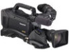
Audio (input) Function Section 15 8 2 12 3 9 4 6 11 1 16 13 14 1. MIC IN (microphone input) jack (XLR, 5-pin) A microphone (optional accessory) is connected here. Power for the microphone comes from this jack. A remote microphone may be connected. When a microphone is used, set the power to ON through the menu option FRONT MIC POWER. The menu item FRONT MIC POWER is found in the screen on the MAIN OPERATION page. > [Preparing for Audio Input] (page 114) 2. AUDIO LEVEL CH1/3 / CH2/4 (audio channel 1/ 3 / 2/4 recording level adjustment) controls With the 3.AUDIO SELECT CH1/3 / CH2/4 (audio channel 1/3 / 2/4 automatic/manual level adjustment selector) switch positioned to [MAN], these controls can be used to adjust the recording levels for Audio Channels 1/2 (With the menu settings 3/4). Note that the controls are designed to be locked. For adjustment, each control must be depressed while turning. 3. AUDIO SELECT CH1/3 / CH2/4 (audio channel 1/3 / 2/4 automatic/manual level adjustment selector) switch Use this switch to select recording level control mode for Audio Channels 1/2 (With the menu settings 3/4). AUTO: Recording level automatically controlled. MAN: Recording level manually controlled. 16 5 10 7 4. AUDIO IN (audio input selector) switch Use this switch to select the signals recorded through Audio Channels 1 - 4. FRONT: Signal from the microphone connected to the 1.MIC IN (microphone input) jack is recorded. W.L. (WIRELESS) : Signal from the slot-in wireless receiver is recorded. REAR: Signal from the audio device connected to the 5.AUDIO IN CH1/3 / CH2/4 (audio input channel 1/3 / 2/4) connectors is recorded. ‹Note When you use stereo microphone (AJ-MC900G optional), set both CH1 and CH2 (With the menu settings CH3, CH4) to [FRONT]. The signal from L CH is recorded to CH1 (With the menu settings CH3) and that from R CH to CH2 (With the menu settings CH4). 5. AUDIO IN CH1/3 / CH2/4 (audio input channel 1/ 3 / 2/4) connectors (XLR, 3-pin) Audio devices or a microphone may be connected here. > [When Using Audio Devices] (page 115) 6. LINE/MIC (line input/mic input) selector switch Used to select the audio signal input from the 5.AUDIO IN CH1/3 / CH2/4 (audio input channel 1/3 / 2/4) connectors. LINE: Audio signal line-input from the audio device is input. MIC: Audio signal from a self-powered (active) microphone is input. (The main unit does not supply power to the remote microphone). 18 Parts and their Functions: Audio (input) Function Section
-
 1
1 -
2
-
3
-
4
-
5
-
6
-
7
-
8
-
9
-
10
-
11
-
12
-
 13
13 -
 14
14 -
 15
15 -
 16
16 -
 17
17 -
 18
18 -
 19
19 -
 20
20 -
 21
21 -
 22
22 -
 23
23 -
24
-
25
-
26
-
27
-
28
-
29
-
30
-
31
-
32
-
33
-
34
-
35
-
36
-
37
-
38
-
39
-
40
-
41
-
42
-
43
-
44
-
45
-
46
-
47
-
48
-
49
-
50
-
51
-
52
-
53
-
54
-
55
-
56
-
57
-
58
-
59
-
60
-
61
-
62
-
63
-
64
-
65
-
66
-
67
-
68
-
69
-
70
-
71
-
72
-
73
-
74
-
75
-
76
-
77
-
78
-
79
-
80
-
81
-
82
-
83
-
84
-
85
-
86
-
87
-
88
-
89
-
90
-
91
-
92
-
93
-
94
-
95
-
96
-
97
-
98
-
99
-
100
-
101
-
102
-
103
-
104
-
105
-
106
-
107
-
108
-
109
-
110
-
111
-
112
-
113
-
114
-
115
-
116
-
117
-
118
-
119
-
120
-
121
-
122
-
123
-
124
-
125
-
126
-
127
-
128
-
129
-
130
-
131
-
132
-
133
-
134
-
135
-
136
-
137
-
138
-
139
-
140
-
141
-
142
-
143
-
144
-
145
-
146
-
147
-
148
-
149
-
150
-
151
-
152
-
153
-
154
-
155
-
156
-
157
-
158
-
159
-
160
-
161
-
162
-
163
-
164
-
165
-
166
-
167
-
168
-
169
-
170
-
171
-
172
-
173
-
174
-
175
-
176
-
177
-
178
-
179
-
180
-
181
-
182
-
183
-
184
-
185
-
186
-
187
-
188
-
189
-
190
-
191
-
192
-
193
-
194
-
195
-
196
-
197
-
198
-
199
-
200
-
201
-
202
-
203
-
204
-
205
-
206
-
207
-
208
 |
 |
