Panasonic P2 HD Camcorder Operating Instructions - Page 31
Microphone holder, Connecting plug
 |
View all Panasonic P2 HD Camcorder manuals
Add to My Manuals
Save this manual to your list of manuals |
Page 31 highlights
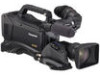
Parts and their Functions 9. Eyepiece ‹Note Do not leave the eyepiece aimed at the sun. Doing so may damage the internal components. 10.Diopter adjustment ring Use this to make adjustments in line with your diopter, in order to obtain optimum clarity in the viewfinder image. The adjustable range of the viewfinder view angle is shown in the following table. Product Number Adjustable range AJ-HVF21KG -0.9 D to -4.4 D For an eyepiece for presbyopia, consult the dealer. 11.Connecting plug 12.Locking ring 13.Microphone holder 14.Viewfinder stopper Used to attach or remove the viewfinder. If, when fitting a large lens, there is insufficient space between the top of the lens and the bottom of the viewfinder, the positions of the slide rails can be shifted upwards slightly by repositioning the screws. a b a. Conventional screw positions b. Reposition and fix 3 screws here to raise the slide rail by approximately 8 mm. 16 15 15.Viewfinder left-right position anchoring ring Used to adjust the side-to-side position of the viewfinder. 16.Viewfinder front-back position anchoring lever Used to adjust the fore-and-aft position of the viewfinder. ‹Note For more information, see th e instruction manual for the viewfinder. 31 Parts and their Functions: Viewfinder
-
 1
1 -
2
-
3
-
4
-
5
-
6
-
7
-
8
-
9
-
10
-
11
-
12
-
13
-
14
-
15
-
16
-
17
-
18
-
19
-
20
-
21
-
22
-
23
-
24
-
25
-
 26
26 -
 27
27 -
 28
28 -
 29
29 -
 30
30 -
 31
31 -
 32
32 -
 33
33 -
 34
34 -
 35
35 -
 36
36 -
37
-
38
-
39
-
40
-
41
-
42
-
43
-
44
-
45
-
46
-
47
-
48
-
49
-
50
-
51
-
52
-
53
-
54
-
55
-
56
-
57
-
58
-
59
-
60
-
61
-
62
-
63
-
64
-
65
-
66
-
67
-
68
-
69
-
70
-
71
-
72
-
73
-
74
-
75
-
76
-
77
-
78
-
79
-
80
-
81
-
82
-
83
-
84
-
85
-
86
-
87
-
88
-
89
-
90
-
91
-
92
-
93
-
94
-
95
-
96
-
97
-
98
-
99
-
100
-
101
-
102
-
103
-
104
-
105
-
106
-
107
-
108
-
109
-
110
-
111
-
112
-
113
-
114
-
115
-
116
-
117
-
118
-
119
-
120
-
121
-
122
-
123
-
124
-
125
-
126
-
127
-
128
-
129
-
130
-
131
-
132
-
133
-
134
-
135
-
136
-
137
-
138
-
139
-
140
-
141
-
142
-
143
-
144
-
145
-
146
-
147
-
148
-
149
-
150
-
151
-
152
-
153
-
154
-
155
-
156
-
157
-
158
-
159
-
160
-
161
-
162
-
163
-
164
-
165
-
166
-
167
-
168
-
169
-
170
-
171
-
172
-
173
-
174
-
175
-
176
-
177
-
178
-
179
-
180
-
181
-
182
-
183
-
184
-
185
-
186
-
187
-
188
-
189
-
190
-
191
-
192
-
193
-
194
-
195
-
196
-
197
-
198
-
199
-
200
-
201
-
202
-
203
-
204
-
205
-
206
-
207
-
208
 |
 |
