Panasonic P2 HD Camcorder Operating Instructions - Page 85
Display Modes and Setting Changes/adjustment Result Messages
 |
View all Panasonic P2 HD Camcorder manuals
Add to My Manuals
Save this manual to your list of manuals |
Page 85 highlights
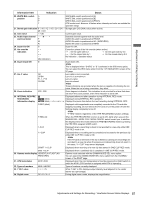
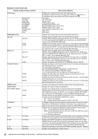
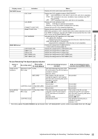
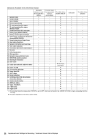
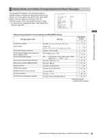
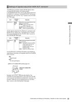
Adjustments and Settings for Recording Display Modes and Setting Changes/adjustment Result Messages The messages that appear on the viewfinder screen to indicate changes to settings and adjustment results may be limited, or set not to appear, through the menu option DISP MODE. This menu option can be found in the screen, which is accessible from the VF page. > For directions on navigating the menu, see [Setting Menu Options] (page 160). # < VF DISPLAY > DISP CONDITION :NORMAL DISP MODE :3 VF OUT :Y VF DTL :05 ZEBRA1 DETECT :070% ZEBRA2 DETECT :085% ZEBRA2 :SPOT LOW LIGHT LVL :35% RC MENU DISP. :OFF MARKER/CHAR LVL :50% SYNCHRO SCAN DISP. :sec Setting change/adjustment result messages and DISP MODE settings Message appears when: CC/ND filter changed. Gain changed. WHITE BAL switch re-positioned. OUTPUT/AUTO KNEE switch positioned at [AUTO KNEE] or [OFF]. Shutter speed/mode changed. White balance adjusted (AWB performed). Black balance adjusted (ABB performed). Extender selected. USER button selected. MARKER SELECT function selected Iris being overridden. The CAC lens is connected or removed. Message FILTER: n (n=1, 2, 3, 4), m (m=A, B, C, D) GAIN: n dB (n=-6, -3, 0, 3, 6, 9, 12, 15, 18, 21, 24, 27, 30) WHITE: n (n=A, B, PRE) AUTO KNEE: ON (or OFF) SS: 1/100 (or 1/60, 1/120, 1/250, 1/500, 1/1000, 1/2000, 11/¢¢.¢ or 1¢¢¢.0d) Example: AWB A OK 3.2 K Example: ABB OK Example: EXTENDER ON Example: UM: S.GAIN 30 dB Example: MKR: A Example: ++ F 5.6 Example: CAC LENS DATA INVALID DISP MODE settings 123 ±±z ±±z ±±z ±zz ±zz ±zz ±zz ±±z ±zz ±±z ±zz ±zz z: Message appears. ±: Message does not appear. 85 Adjustments and Settings for Recording : Viewfinder Screen Status Displays
-
 1
1 -
2
-
3
-
4
-
5
-
6
-
7
-
8
-
9
-
10
-
11
-
12
-
13
-
14
-
15
-
16
-
17
-
18
-
19
-
20
-
21
-
22
-
23
-
24
-
25
-
26
-
27
-
28
-
29
-
30
-
31
-
32
-
33
-
34
-
35
-
36
-
37
-
38
-
39
-
40
-
41
-
42
-
43
-
44
-
45
-
46
-
47
-
48
-
49
-
50
-
51
-
52
-
53
-
54
-
55
-
56
-
57
-
58
-
59
-
60
-
61
-
62
-
63
-
64
-
65
-
66
-
67
-
68
-
69
-
70
-
71
-
72
-
73
-
74
-
75
-
76
-
77
-
78
-
79
-
 80
80 -
 81
81 -
 82
82 -
 83
83 -
 84
84 -
 85
85 -
 86
86 -
 87
87 -
 88
88 -
 89
89 -
 90
90 -
91
-
92
-
93
-
94
-
95
-
96
-
97
-
98
-
99
-
100
-
101
-
102
-
103
-
104
-
105
-
106
-
107
-
108
-
109
-
110
-
111
-
112
-
113
-
114
-
115
-
116
-
117
-
118
-
119
-
120
-
121
-
122
-
123
-
124
-
125
-
126
-
127
-
128
-
129
-
130
-
131
-
132
-
133
-
134
-
135
-
136
-
137
-
138
-
139
-
140
-
141
-
142
-
143
-
144
-
145
-
146
-
147
-
148
-
149
-
150
-
151
-
152
-
153
-
154
-
155
-
156
-
157
-
158
-
159
-
160
-
161
-
162
-
163
-
164
-
165
-
166
-
167
-
168
-
169
-
170
-
171
-
172
-
173
-
174
-
175
-
176
-
177
-
178
-
179
-
180
-
181
-
182
-
183
-
184
-
185
-
186
-
187
-
188
-
189
-
190
-
191
-
192
-
193
-
194
-
195
-
196
-
197
-
198
-
199
-
200
-
201
-
202
-
203
-
204
-
205
-
206
-
207
-
208
 |
 |
