Panasonic P2 HD Camcorder Operating Instructions - Page 89
Settings of signals output from MON OUT connector, Variable, range, Remarks, HD SDI, MON OUT CHARACTER
 |
View all Panasonic P2 HD Camcorder manuals
Add to My Manuals
Save this manual to your list of manuals |
Page 89 highlights
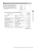
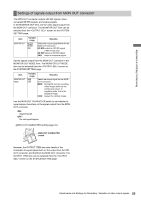
Adjustments and Settings for Recording Settings of signals output from MON OUT connector The MON OUT connector outputs HD SDI signals, downconverted SD SDI signals, and analog signals. In the MONITOR OUT item, set the video signal output from the MON OUT connector. The MONITOR OUT item can be selected from the screen on the SYSTEM SETTING page. Item MONITOR OUT Variable range Remarks HD SDI SD SDI VBS Select the output signal format for the MON OUT connector. HD SDI:output an HD SDI signal. (1080i mode only) SD SDI:output an SD SDI signal. VBS: output a composite signal. Set the signals output from the MON OUT connector in the MONITOR OUT MODE item. The MONITOR OUT MODE item can be selected from the screen on the SYSTEM SETTING page. Item MONITOR OUT MODE Variable range Remarks MEM Select the output signal for the MON CAM OUT connector. MEM: During EE such as recording, video images taken by the camera are output. In playback mode, this is the playback image. CAM: always the camera image. Use the MON OUT CHARACTER switch to set whether to superimpose characters on the signals output from the MON OUT connector. ON: Superimpose. OFF: Do not superimpose. > [MON OUT CHARACTER switch] (page 22) MON OUT CHARACTER switch However, the OUTPUT ITEM item sets details of the characters to superimpose both on the output from the SDI OUT connector, and that from the MON OUT connector. The OUTPUT ITEM item can be selected from the screen on the SYSTEM SETTING page. 89 Adjustments and Settings for Recording : Selection of video output signals
-
 1
1 -
2
-
3
-
4
-
5
-
6
-
7
-
8
-
9
-
10
-
11
-
12
-
13
-
14
-
15
-
16
-
17
-
18
-
19
-
20
-
21
-
22
-
23
-
24
-
25
-
26
-
27
-
28
-
29
-
30
-
31
-
32
-
33
-
34
-
35
-
36
-
37
-
38
-
39
-
40
-
41
-
42
-
43
-
44
-
45
-
46
-
47
-
48
-
49
-
50
-
51
-
52
-
53
-
54
-
55
-
56
-
57
-
58
-
59
-
60
-
61
-
62
-
63
-
64
-
65
-
66
-
67
-
68
-
69
-
70
-
71
-
72
-
73
-
74
-
75
-
76
-
77
-
78
-
79
-
80
-
81
-
82
-
83
-
 84
84 -
 85
85 -
 86
86 -
 87
87 -
 88
88 -
 89
89 -
 90
90 -
 91
91 -
 92
92 -
 93
93 -
 94
94 -
95
-
96
-
97
-
98
-
99
-
100
-
101
-
102
-
103
-
104
-
105
-
106
-
107
-
108
-
109
-
110
-
111
-
112
-
113
-
114
-
115
-
116
-
117
-
118
-
119
-
120
-
121
-
122
-
123
-
124
-
125
-
126
-
127
-
128
-
129
-
130
-
131
-
132
-
133
-
134
-
135
-
136
-
137
-
138
-
139
-
140
-
141
-
142
-
143
-
144
-
145
-
146
-
147
-
148
-
149
-
150
-
151
-
152
-
153
-
154
-
155
-
156
-
157
-
158
-
159
-
160
-
161
-
162
-
163
-
164
-
165
-
166
-
167
-
168
-
169
-
170
-
171
-
172
-
173
-
174
-
175
-
176
-
177
-
178
-
179
-
180
-
181
-
182
-
183
-
184
-
185
-
186
-
187
-
188
-
189
-
190
-
191
-
192
-
193
-
194
-
195
-
196
-
197
-
198
-
199
-
200
-
201
-
202
-
203
-
204
-
205
-
206
-
207
-
208
 |
 |
