Panasonic P2 HD Camcorder Operating Instructions - Page 88
Selection of video output signals, Settings of signals output from SDI OUT connector
 |
View all Panasonic P2 HD Camcorder manuals
Add to My Manuals
Save this manual to your list of manuals |
Page 88 highlights
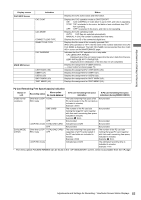
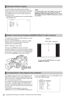
Selection of video output signals The unit employs the SDI OUT connector and the MON OUT connector as connectors for outputting video signals. Settings of signals output from SDI OUT connector The type of output signal from the SDI OUT connector is in accordance with the SYSTEM MODE item. Additionally, the signal output from the SDI OUT connector is switched from the SDI OUT MODE item. The SYSTEM MODE can be selected from the screen on the SYSTEM SETTING page, and the SDI OUT MODE can be selected from the screen on the SYSTEM SETTING page. Item SDI OUT MODE Variable range MEM CAM Remarks MEM: During EE such as recording, video images taken by the camera are output. Meanwhile, signals on the P2 card are output during playback. CAM: Camera images are output at all times. Set the characters to be superimposed on the signals output from the SDI OUT connector in the OUTPUT ITEM and SDI OUT CHAR items. Items can be selected from the screen on the SYSTEM SETTING page. Item OUTPUT ITEM SDI OUT CHAR Variable range Remarks MENU ONLY TC STATUS OFF ON Set the characters to be superimposed on the output signals from the VIDEO OUT connector. MENU ONLY: The menu screen is superimposed only when the menu is accessed. This normally displays nothing. TC: Time codes are superimposed (when the menu is accessed, the menu screen is superimposed.) STATUS: The characters that are the same as the characters superimposed in the viewfinder screen are superimposed. (When the menu is accessed, the menu screen is superimposed.) Select whether to superimpose characters on the image output from the SDI OUT connector. OFF: Do not superimpose. ON: Superimpose. ‹Note The content of the superimposed characters is the same as that superimposed on video output from the MON OUT connector 88 Adjustments and Settings for Recording : Selection of video output signals
-
 1
1 -
2
-
3
-
4
-
5
-
6
-
7
-
8
-
9
-
10
-
11
-
12
-
13
-
14
-
15
-
16
-
17
-
18
-
19
-
20
-
21
-
22
-
23
-
24
-
25
-
26
-
27
-
28
-
29
-
30
-
31
-
32
-
33
-
34
-
35
-
36
-
37
-
38
-
39
-
40
-
41
-
42
-
43
-
44
-
45
-
46
-
47
-
48
-
49
-
50
-
51
-
52
-
53
-
54
-
55
-
56
-
57
-
58
-
59
-
60
-
61
-
62
-
63
-
64
-
65
-
66
-
67
-
68
-
69
-
70
-
71
-
72
-
73
-
74
-
75
-
76
-
77
-
78
-
79
-
80
-
81
-
82
-
 83
83 -
 84
84 -
 85
85 -
 86
86 -
 87
87 -
 88
88 -
 89
89 -
 90
90 -
 91
91 -
 92
92 -
 93
93 -
94
-
95
-
96
-
97
-
98
-
99
-
100
-
101
-
102
-
103
-
104
-
105
-
106
-
107
-
108
-
109
-
110
-
111
-
112
-
113
-
114
-
115
-
116
-
117
-
118
-
119
-
120
-
121
-
122
-
123
-
124
-
125
-
126
-
127
-
128
-
129
-
130
-
131
-
132
-
133
-
134
-
135
-
136
-
137
-
138
-
139
-
140
-
141
-
142
-
143
-
144
-
145
-
146
-
147
-
148
-
149
-
150
-
151
-
152
-
153
-
154
-
155
-
156
-
157
-
158
-
159
-
160
-
161
-
162
-
163
-
164
-
165
-
166
-
167
-
168
-
169
-
170
-
171
-
172
-
173
-
174
-
175
-
176
-
177
-
178
-
179
-
180
-
181
-
182
-
183
-
184
-
185
-
186
-
187
-
188
-
189
-
190
-
191
-
192
-
193
-
194
-
195
-
196
-
197
-
198
-
199
-
200
-
201
-
202
-
203
-
204
-
205
-
206
-
207
-
208
 |
 |
