Panasonic P2 HD Camcorder Operating Instructions - Page 23
MARKER SEL, MODE CHK / MENU CANCEL, OUTPUT/AUTO KNEE selector switch
 |
View all Panasonic P2 HD Camcorder manuals
Add to My Manuals
Save this manual to your list of manuals |
Page 23 highlights
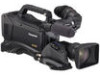
Parts and their Functions 17.BUSY (operation mode display) lamp This lamp indicates the active status of the SD memory card. It stays illuminated when the card is active. ‹Note While the lamp is on, do not insert or remove the card. The SD memory card might break. 18.Focal plane index ( ) This symbol indicates the focal plane of the CCD sensor. It provides a reference for making accurate focal distance measurements from the subject. 19.MARKER SEL, MODE CHK / MENU CANCEL switch This is the dual purpose spring switch for MARKER selection and MODE CHECK/MENU CANCEL. When you press this switch on the side of this unit, the marker displayed by the viewfinder changes. Press this button on the side of this unit to switch the information display screen for A and B, the two types of markers set with the menu, A (A marker display) > B (B marker display) > OFF (no marker display). When the power is turned on, the last selected indication before powerdown appears. > [Marker Check Screen Displays (MARKER SELECT button function)] (page 86)] When you pull this button toward you, a six screen display for camera setting status (STATUS screen display, !LED screen display, FUNCTION screen display, AUDIO screen display, CAC screen display, USER SW screen display) switch sequentially on the viewfinder. The camera output signal is not affected. The display goes out in about 5 seconds. When the selected screen is displayed, the display will continue while you press the button. While displaying the menu, this button works as a switch to cancel changed setting values. 20.Gain selector switch Use this switch to select video amplifier gain, according to lighting conditions under which you are shooting. The values for L, M, and H can be preset using menu options. These are factory-set to 0 dB for L, 6 dB for M, and 12 dB for H. 21. OUTPUT/AUTO KNEE selector switch Used to select the video signals sent from the camera unit to the memory, viewfinder and video monitor. CAM. AUTO KNEE ON: Video being recorded through the camera is sent with the auto knee circuit activated. It is also possible to assign the DRS (Dynamic Range Stretcher) function instead of the AUTO KNEE function. CAM. AUTO KNEE OFF: Video being recorded through the camera is sent in manual knee mode. BARS: Color bar signal is output. The AUTO KNEE circuit does not work. You can select between four types of color bar signal. > [COLOR BARS] (page 184). ‹Note With the factory settings, TEST TONE is output to all 4 channels of audio when OUTPUT/AUTO KNEE switch is set to [BARS] and CH1 of AUDIO IN switch is set to [FRONT]. The output method of TEST TONE can be changed in the TEST TONE menu option. > [TEST TONE] (page 190) Auto Knee function Usually, when you adjust levels to shoot people or scenery against a strongly lit background, the background will be totally whited-out, with buildings and other objects blurred. In this case, the AUTO KNEE function reproduces the background clearly. This function is effective when: • The subject is a person positioned in the shade under a clear sky. • The subject is a person inside a car or building, and you also want to capture the background visible through a window. • The subject is a high-contrast scene. 22. WHITE BAL (white balance memory selector) switch Used to select the white balance adjustment method. PRST: A or B: Use this when you have no time to adjust the white balance. The value for the white balance is factory-set to 3200 K. It can be changed to any color temperature using a menu option. > [Setting Color Temperature Manually] (page 51). Pressing the 4. AUTO W/B BAL Switch toward [AWB] automatically adjusts the white balance, saving the adjusted value in Memory A or B. Also, with menu settings you can assign B to auto tracking white balance (ATW) of the auto tracking mode. > [Adjusting the White Balance] (page 49). 23 Parts and their Functions: Shooting and Recording/Playback Functions Section
-
 1
1 -
2
-
3
-
4
-
5
-
6
-
7
-
8
-
9
-
10
-
11
-
12
-
13
-
14
-
15
-
16
-
17
-
 18
18 -
 19
19 -
 20
20 -
 21
21 -
 22
22 -
 23
23 -
 24
24 -
 25
25 -
 26
26 -
 27
27 -
 28
28 -
29
-
30
-
31
-
32
-
33
-
34
-
35
-
36
-
37
-
38
-
39
-
40
-
41
-
42
-
43
-
44
-
45
-
46
-
47
-
48
-
49
-
50
-
51
-
52
-
53
-
54
-
55
-
56
-
57
-
58
-
59
-
60
-
61
-
62
-
63
-
64
-
65
-
66
-
67
-
68
-
69
-
70
-
71
-
72
-
73
-
74
-
75
-
76
-
77
-
78
-
79
-
80
-
81
-
82
-
83
-
84
-
85
-
86
-
87
-
88
-
89
-
90
-
91
-
92
-
93
-
94
-
95
-
96
-
97
-
98
-
99
-
100
-
101
-
102
-
103
-
104
-
105
-
106
-
107
-
108
-
109
-
110
-
111
-
112
-
113
-
114
-
115
-
116
-
117
-
118
-
119
-
120
-
121
-
122
-
123
-
124
-
125
-
126
-
127
-
128
-
129
-
130
-
131
-
132
-
133
-
134
-
135
-
136
-
137
-
138
-
139
-
140
-
141
-
142
-
143
-
144
-
145
-
146
-
147
-
148
-
149
-
150
-
151
-
152
-
153
-
154
-
155
-
156
-
157
-
158
-
159
-
160
-
161
-
162
-
163
-
164
-
165
-
166
-
167
-
168
-
169
-
170
-
171
-
172
-
173
-
174
-
175
-
176
-
177
-
178
-
179
-
180
-
181
-
182
-
183
-
184
-
185
-
186
-
187
-
188
-
189
-
190
-
191
-
192
-
193
-
194
-
195
-
196
-
197
-
198
-
199
-
200
-
201
-
202
-
203
-
204
-
205
-
206
-
207
-
208
 |
 |
