Belkin F5D7632-4_V3000 User Manual - Page 7
Knowing your Router
 |
View all Belkin F5D7632-4_V3000 manuals
Add to My Manuals
Save this manual to your list of manuals |
Page 7 highlights
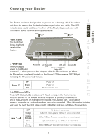
Knowing your Router section 1 The Router has been designed to be placed on a desktop. All of the cables exit from the rear of the Router for better organization and utility. The LED indicators are easily visible on the front of the Router to provide you with 2 information about network activity and status. 3 Front Panel The illustration 4 shows the front panel of the 5 Router: 6 7 1. Power LED Power LED LAN Status LED ADSL LED Internet LED When you apply power to the Router (1-4) Wireless LAN (WLAN) Status LED 8 or restart it, a short period of time elapses while the Router boots up. When the Router has completely booted up, the Power LED becomes a GREEN light, 9 indicating the Router is ready for use. OFF Power off 10 Power Green Power on Red Router failed to start 11 2. LAN Status LEDs These LAN Status LEDs are labeled 1-4 and correspond to the numbered 12 ports on the rear of the Router. When a computer is properly connected to one of the LAN ports on the rear of the Router, the LED will light. Solid GREEN means a computer or a network-enabled device is connected. When information is being sent over the port, the LED blinks rapidly. ORANGE indicates a 10Base-T connection. LAN - OFF No device is connected Orange Ethernet link is up and 10Base-T device connected bOlrinaknig�n�e�g W��h�en�1�0�B��ase-T device transmitting or receiving data Green Ethernet link is up and 100Base-T connected Green blinking When 100Base-T device transmitting or receiving data 7
-
 1
1 -
 2
2 -
 3
3 -
 4
4 -
 5
5 -
 6
6 -
 7
7 -
 8
8 -
 9
9 -
 10
10 -
 11
11 -
 12
12 -
13
-
14
-
15
-
16
-
17
-
18
-
19
-
20
-
21
-
22
-
23
-
24
-
25
-
26
-
27
-
28
-
29
-
30
-
31
-
32
-
33
-
34
-
35
-
36
-
37
-
38
-
39
-
40
-
41
-
42
-
43
-
44
-
45
-
46
-
47
-
48
-
49
-
50
-
51
-
52
-
53
-
54
-
55
-
56
-
57
-
58
-
59
-
60
-
61
-
62
-
63
-
64
-
65
-
66
-
67
-
68
-
69
-
70
-
71
-
72
-
73
-
74
-
75
-
76
-
77
-
78
-
79
-
80
-
81
-
82
-
83
-
84
-
85
-
86
-
87
-
88
-
89
-
90
-
91
-
92
-
93
-
94
-
95
-
96
-
97
-
98
-
99
-
100
-
101
-
102
-
103
-
104
-
105
-
106
-
107
-
108
 |
 |
