Brother International HL-2600CN Service Manual
Brother International HL-2600CN Manual
 |
View all Brother International HL-2600CN manuals
Add to My Manuals
Save this manual to your list of manuals |
Brother International HL-2600CN manual content summary:
- Brother International HL-2600CN | Service Manual - Page 1
Brother Color Laser Printer SERVICE MANUAL MODEL: HL-2600CN Read this manual thoroughly before maintenance work. Keep this manual in a convenient place for quick and easy reference at all times. October 2001 SM-PRN023 - Brother International HL-2600CN | Service Manual - Page 2
: The brother logo is a registered trademark of Brother Industries, Ltd. Apple, the Apple Logo, and Macintosh are trademarks, registered in the United States and MS-DOS are registered trademarks of Microsoft Corporation. Windows is a registered trademark of Microsoft Corporation in the U.S. - Brother International HL-2600CN | Service Manual - Page 3
to maintain the high printing quality and performance of the printer. This service manual covers the HL-2600CN color laser printer. This manual consists of the following chapters: CHAPTER I : OUTLINE OF PRODUCT Features, parts names, internal structure, and description of the control panel. CHAPTER - Brother International HL-2600CN | Service Manual - Page 4
...III-2 2.2 Unpack the Starter Kit...III-4 3. INSTALLATION WORK III-5 3.1 Install the Fuser Cleaner and Oil Bottle III-5 3.2 Install the OPC Belt Cartridge III-6 3.3 Install the Toner Cartridge to the Printer III-8 3.4 Test Print...III-9 CHAPTER IV STRUCTURE OF SYSTEM COMPONENTS IV-1 1. BASIC - Brother International HL-2600CN | Service Manual - Page 5
VI-4 1.3 Periodic Maintenance Parts and Maintenance Cycle VI-17 2. PERIODIC MAINTENANCE PROCEDURES VI-20 2.1 OPC Belt Cartridge Replacement VI-20 2.2 Fusing Unit Replacement VI-23 2.3 Transfer Roller 2 Replacement VI-27 2.4 Paper Discharger Unit Replacement VI-30 2.5 Drum Cleaner 2 Replacement - Brother International HL-2600CN | Service Manual - Page 6
of the Printer...VII-63 4.7 Fusing Unit...VII-68 CHAPTER VIII TROUBLESHOOTING VIII-1 1. OUTLINE OF TROUBLESHOOTING VIII-2 2. OPERATOR CALL VIII-3 2.1 Video Controller Mode ...VIII-3 2.2 Engine Controller Mode VIII-6 3. PAPER TRANSPORT ERROR VIII-8 3.1 Feed Jam ...VIII-8 3.2 Inner Jam ...VIII - Brother International HL-2600CN | Service Manual - Page 7
labels on the back of the printer indicates compliance with the FDA regulations and must be attached to laser products marketed in the United States. Caution Use of controls, adjustments or performance of procedures other than those specified in this manual may result in hazardous radiation exposure - Brother International HL-2600CN | Service Manual - Page 8
KLASSE 1 PRODUKT This printer has a Class 3B Laser Diode which emits invisible laser radiation in the Scanner Unit. The Scanner Unit should not be opened specified in this manual may result in hazardous radiation exposure. The following caution label is attached near the scanner unit. 5mW 780nm-800nm - Brother International HL-2600CN | Service Manual - Page 9
not related to your required operation(s). 4) Repair and replacement of parts should be performed by trained and qualified persons only. Operators should to safety messages in this manual. Carefully read all the safety messages set out in this manual and also in the - Brother International HL-2600CN | Service Manual - Page 10
accordance with the manual supplied with the printer. WARNING HOT SURFACE The Fusing Unit reaches a temperature of approx.170°C and adjacent parts are also very hot. When you need to change the cleaning pad or remove jammed paper, wait about 20 minutes after opening the paper exit unit to allow the - Brother International HL-2600CN | Service Manual - Page 11
which may cause irritation to the eyes and respiratory organs if inhaled. Handle the toner cartridge, waste toner pack and developing unit carefully so as not to spill the toner. CAUTION POWER CORDS & PLUGS This printer is equipped with a 3-wire power cord fitted with a 3-pronged plug (bi-polar plug - Brother International HL-2600CN | Service Manual - Page 12
CAUTION Do not lean against or apply any excessive force to the paper cassette, open cover of Duplex unit. Otherwise it may cause the product to decline or fall down and result in the injuries. vi - Brother International HL-2600CN | Service Manual - Page 13
1 3 1. Hot Caution Label 2. Laser Caution Label 2 170 C/338 F 5mW 780nm-800nm DANGER- INVISIBLE LASER RADIATION WHEN OPEN. AVOID DIRECT EXPOSURE TO BEAM. VORSICHT- UNSICHTBARE LASERSTRAHLUNG, WENN ABDECKUNG GEÖFFNET UND SICHERHEITSVERRIEGELUNG ÜBERBRÜCKT. NICHT DEM STRAHL - Brother International HL-2600CN | Service Manual - Page 14
3. Rating Label (For US) (For Europe) (Jam label) viii - Brother International HL-2600CN | Service Manual - Page 15
remove the toner cartridges, the OPC belt cartridge and the waste toner pack from the printer to prevent toner spill in the printer or damage of the toner cartridge and the OPC belt cartridge. When shipping the printer, remove the oil bottle and the fuser cleaner from the fusing unit. After removing - Brother International HL-2600CN | Service Manual - Page 16
- Brother International HL-2600CN | Service Manual - Page 17
- Brother International HL-2600CN | Service Manual - Page 18
, Magenta and Yellow) single-sided pages at 5% coverage. The one piece, easy-to-replace toner cartridges do not require difficult maintenance. Universal Media Cassette This printer loads paper automatically from the media cassette. Since the media cassette is a universal type, a number of different - Brother International HL-2600CN | Service Manual - Page 19
, such as BRAdmin Professional for the administrator and Brother network printing software, are included in the CD-ROM supplied with the HL-2600CN printer. For setup, see the Network User's Guide. Automatic Interface Selection The printer can automatically select the bi-directional parallel, USB - Brother International HL-2600CN | Service Manual - Page 20
(UPC-E) UPC-A CCITT G3/G4 Since the printer supports the CCITT G3/G4 format in addition to Toner Save Mode The printer has an economical toner save mode. This mode allows you to reduce the printer running cost substantially in addition to the improved life expectancy of the toner cartridge - Brother International HL-2600CN | Service Manual - Page 21
2. PARTS NAMES & FUNCTIONS 10. Paper stopper A 2. Control Panel 1. Top Cover ASSY 2 11. Paper stopper B 5. Power Button Media Cassette 3. Front Cover 2 Fig.1-1 9. Paper Exit Unit Cover 2 8. Controller Box 6. Power Inlet 7. Rear Access Cover 4. Paper Exit Unit Fig.1-2 - Brother International HL-2600CN | Service Manual - Page 22
a front enclosure, opened when replacing a toner cartridge or waste toner pack. To exit a printed paper onto a top cover ASSY 2, acting also as paper tray for printed paper. To be opened when replacing an OPC belt cartridge. To operate power-on and off to the printer. (Push for On/Off operation) To - Brother International HL-2600CN | Service Manual - Page 23
2.OPC Belt Cartridge 1.Toner Cartridge (K, Y, M, C) 5.Transfer Unit 2 7.Paper Discharger 8.Transfer Roller 2 6.Transfer Drum 2 12.Registration Roller 2 10.Paper Pick-up Roller K Y M C Fig.1-3 11.Scanner Unit 9.Media Cassette No. Components Name 1 Toner Cartridge 2 OPC Belt Cartridge 3 Drum - Brother International HL-2600CN | Service Manual - Page 24
further engine settings are required, use the Engine Controller Mode. 4.2 Engine Controller Mode The printer goes into the Engine Controller Mode when power is turned on by pressing the power button on the actual control panel or in the user's guide. Refer to Chapter V for detailed information. I-7 - Brother International HL-2600CN | Service Manual - Page 25
1 K CM Y 3 2 4 Power Ready Data 5 6 7 Alarm Go Job Cancel 9 8 10 Secure Print Menu 12 11 13 Reprint Back Set Fig.1-4 No. LED / Button Name 1 LCD: 16 character by 2 lines 2 Power LED 3 Ready LED 4 Data LED 5 Go button 6 Job Cancel button 7 Alarm LED 8 Secure - Brother International HL-2600CN | Service Manual - Page 26
CHAPTER II SPECIFICATIONS - Brother International HL-2600CN | Service Manual - Page 27
2.5.1 Printable Media & Cassette Capacity II-5 2.5.2 Printed Output...II-6 2.5.3 Recommended Paper Specifications II-6 2.5.4 Effective Printing Area II-6 2.5.5 Paper Feed Jam Rate...II-8 - Brother International HL-2600CN | Service Manual - Page 28
SPECIFICATIONS WARNING Use the power supply cable supplied with the printer, or a similar cable complying with the following specification (3-wire For details of other power supply cables, refer to the parts reference list. ** For rating labels, refer to the Safety Instruction on Page vi. II-1 - Brother International HL-2600CN | Service Manual - Page 29
(when loading A4/Letter-size paper by face down print delivery from standard upper cassette feed) Print media: Toner in a single-color single-component cartridge Life Expectancy: 12,000 single-sided pages/cartridge (Black) 7,200 single-sided pages/cartridge (Cyan, Magenta, Yellow) Note: These - Brother International HL-2600CN | Service Manual - Page 30
The standard memory fitted can vary depending on the printer model and country Control panel: 8 buttons, 4 LEDs mm (19.7 x 20.5 x 21.9 inches) with the optional lower tray unit fitted Weight: Approx. 39kg (86lbs.) Approx. 54.4kg with the optional lower tray unit and toner cartridges fitted II-3 - Brother International HL-2600CN | Service Manual - Page 31
® based management utility Firmware update: 8MB flash ROM. Use BRAdmin Professional when upgrading print server software or BOOTP, TFTP PUT/GET or IPX for Netware. Supplied software: BRAdmin Professional (for Windows® 95/98/ME/NT 4.0/2000/XP) Driver Deployment Wizard (for Windows® 95/98/ME - Brother International HL-2600CN | Service Manual - Page 32
& Cassette Capacity The standard media cassette (upper cassette) is supplied with the printer. The optional lower tray unit and the optional Legal cassette can also be installed. 1) Printable Media: Plain paper / Transparency / Thick Stock / Label / Envelope 2) Printable size: (Refer to the list - Brother International HL-2600CN | Service Manual - Page 33
15 85 ± 2 1010 ~ 1011 Long Measurement Condition: 17.5 ~ 27.0°C, 50 ~ 70%RH Note: Keep the paper sealed in the bag as supplied and do not open the paper bag until the paper is required for use. 2.5.4 Effective Printing Area (1) Printable area A F E C E BD F The effective printing area means - Brother International HL-2600CN | Service Manual - Page 34
33" (2,498 dots) E 3.4mm 0.13" (40 dots) 4.23mm 0.17" (50 dots) F 4.23mm 0.17" (50 dots) (Note that the paper sizes indicated here should conform to the nominal dimensions specified by JIS.) A4 paper must accommodate 80 characters printed in pica pitch (203.2 mm). The dot size is based on 300 dpi - Brother International HL-2600CN | Service Manual - Page 35
5mm Non guarantee area Non printable area 3mm 42mm 16mm 4mm Print guarantee area 4mm COM10:68mm DL:40mm COM10:68mm DL:40mm 2.5.5 Paper Feed Jam Rate Less than 1 misfeed per 2000 pages under normal environmental conditions. Less than 1 misfeed per 1000 pages outside the normal environmental - Brother International HL-2600CN | Service Manual - Page 36
3. ENVIRONMENTAL CONDITION 3.1 Ambient Temperature / Humidity / Altitude (1) Under Operational conditions: 10.0 32.5 C, 20 80%RH (See the figure below.) Ambient Humidity (%RH) 80 70 60 Zone A Recommended Condition; 50 17.5 27 C 40 50 70%RH Zone B Operation Area 20 other than Zone A. 0 - Brother International HL-2600CN | Service Manual - Page 37
The following defines the storage and transportation environment of printers that have been packed according to Brother specification. However, this section does not cover the OPC belt cartridge and toner cartridges. Temperature Humidity Period of Storage Other Atmosphere Normal Conditions Severe - Brother International HL-2600CN | Service Manual - Page 38
- Brother International HL-2600CN | Service Manual - Page 39
- Brother International HL-2600CN | Service Manual - Page 40
ammonia. (e) Users should select a location with good ventilation and set the printer on a flat surface. (f) Users should check printer. Table 50cm (20") 20cm (8") 70cm (28") 50cm (19.7") Paper Exit Side Front Side Power Cord 54cm (21.3") 50cm (20") Fig.3-1 The space in front of the printer - Brother International HL-2600CN | Service Manual - Page 41
when it is covered by the vinyl bag because it is slippery and may result in damage and injury if dropped. 2.1 Unpacking the Printer Refer to Fig.3-2 on the next page. 1) Cut the P.P band (2 pieces). 2) Remove the plastic joints (4 locations). 3) Remove the outer box tape. 4) Open the top of - Brother International HL-2600CN | Service Manual - Page 42
(Oil) Engine Top Cushion Sleeve Scotch Tape (w:25mm) Polyethylene Bag (EN) F Tape (w:38mm) Base Packing Fig.3-2 III-3 Starter Kit Packing (U) Toner Partition Packing Polyethylene Bag (T) #23 Polyethylene Bag (CL) P.P Band (w:15.5mm) Outer Box Tape (w:75mm) Silica Gel (ST) Silica Gel (EN - Brother International HL-2600CN | Service Manual - Page 43
Appearance Quantity 1 Toner Cartridge (Y,M,C,K) Y(Yellow) M(Magenta) 4 C(Cyan) K(Black) 2 OPC Belt Cartridge 1 3 Oil Bottle 1 4 Fuser Cleaner Fuser Cleaner 1 Spuit CAUTION When shipping the printer, remove the oil bottle and the fuser cleaner from the fusing unit. After removing - Brother International HL-2600CN | Service Manual - Page 44
3. INSTALLATION WORK Install the unit parts of the starter kit into the printer according to the following procedures: 3.1 Install the Fuser Cleaner and Oil Bottle 1) Open the paper exit cover. Pressure has been released by the fusing release lever between the fuser roller and back-up roller while - Brother International HL-2600CN | Service Manual - Page 45
or removing the OPC belt, be sure to open the front cover first. Failure to do so will cause the OPC belt to be damaged due to contact with the toner cartridges. Paper exit unit cover 2 2) Release the belt cartridge lock levers (left & right). Front cover Fig.3-6 Belt cartridge lock lever Fig - Brother International HL-2600CN | Service Manual - Page 46
OPC belt cartridge 5) Install the new OPC belt cartridge into the printer, along the guide of belt cartridge lock lever provided at both sides. OPC belt cartridge Fig.3-8 Tension release pin 6) Set the belt cartridge lock lever at both sides (left and right). 7) Close the paper exit unit - Brother International HL-2600CN | Service Manual - Page 47
3) Remove the seal tape and remove a protective cover of toner cartridge. Fig.3-11 Protective cover 4) Push the new toner cartridge along the guide into the printer. Toner cartridge Fig.3-12 5) Installation order of toner cartridge in terms of color shall be Cyan (C), Magenta (M), Yellow - Brother International HL-2600CN | Service Manual - Page 48
3.4 Test Print 1) Make sure the printer power button is off. Do not connect the interface cable. Fig.3-15 2) Connect the AC power cord to the printer, and then plug it into the AC outlet. 3) Turn on the power button. Fig.3-16 Fig.3-17 III-9 - Brother International HL-2600CN | Service Manual - Page 49
READY message will appear. Control panel Power K C MY Ready NETWORK READY HL-2600CN Data Alarm Go Job Cancel Secure Print Reprint Back Set Unfold the tray extension flap Fig.3-18 5) Press the Go button. The printer will print a test page. Check that the test page is printed correctly - Brother International HL-2600CN | Service Manual - Page 50
CHAPTER IV STRUCTURE OF SYSTEM COMPONENTS - Brother International HL-2600CN | Service Manual - Page 51
1.1 Print System and Transfer System IV-6 1.1.1 Structure of the Printer IV-7 1.1.2 Basic Structure of the Printing System IV-8 1.1.3 Details of Each Process IV-10 1.2 Scanning System...IV-21 1.3 Paper Transportation System IV-23 1.4 Fusing Unit...IV-25 2. STRUCTURE OF THE CONTROL SYSTEM IV-27 - Brother International HL-2600CN | Service Manual - Page 52
Drum Second Transfer Part Drum Cleaner Unit (4) Paper Transport System The paper transport system consists of the following 5 (five) functional parts and picks up paper from the media cassette, separates the paper from the transfer drum and exits it from the printer body after fusing the toner - Brother International HL-2600CN | Service Manual - Page 53
Paper Exit Unit Paper Exit Drum Cleaner Unit Main Motor MM Develope Motor DM I/F Controller Fusing Unit Transfer Unit AC Discharger Unit Transfer Roller Fix Paper Discharger Second Transfer Drum Cleaning Operation Transfer Drum First Transfer OPC Belt K Y Development M C MCTL I/F - Brother International HL-2600CN | Service Manual - Page 54
color combination as shown in Fig.4-4 a . (c) The toner image formed on the transfer drum is transferred to the transported paper as shown in Fig.4-4 b . (d) The toner on the paper is fused by the thermal fixing unit to fix the toner image onto the paper as shown in Fig.4-4 c . Summarizing the above - Brother International HL-2600CN | Service Manual - Page 55
Transfer Drum OPC Belt Cartridge Toner Cartridge K Y M C Fig.4-3 a . First Transfer Toner a MM M CCC Y YY CC Y YY Transfer Drum b . Second Transfer YYY YYY b MMM C C C CC Paper C . Fusing Red CR Cyan Green C GR Paper Fig.4-4 IV-4 - Brother International HL-2600CN | Service Manual - Page 56
an aluminum deposit layer in between. The OPC belt is located as shown in Fig.4-5 as the main part of the print system. OPC Belt OPC Belt Cartridge Toner Cartridge K Transfer Drum Y M C Fig.4-5 Electrode Fig.4-6 Scanner Unit Photoconductor(OPC) Aluminum deposit layer Insulator Material IV-5 - Brother International HL-2600CN | Service Manual - Page 57
having the OPC belt as the main part and the transfer system having the transfer drum as the main part. Color OPC Belt Cleaning KYMC 5 Belt Discharge OPC Belt KYMC 4 Transfer Drum(First Transfer) Transfer Drum K Y M C Transfer System 7 Second Transfer(Paper) 9 Transfer Drum Cleaning 8 Paper - Brother International HL-2600CN | Service Manual - Page 58
1.1.1 Structure of the Printer No. Component Part 1 Charger 2 Scanner Unit 3 Toner Cartridge 4 OPC Belt Cartridge 5 Transfer Drum 6 Belt Discharger Erase Lamp 7 Cleaning Blade 8 Transfer Roller 9 Paper Discharger 10 Drum Cleaner 11 Fusing Unit 12 Paper Exit Unit 13 Registration Roller - Brother International HL-2600CN | Service Manual - Page 59
power supply DBV. iv) The frame potential of the transfer drum is GND. Fuser Unit Cleaning Unit FCBV Cleaning Burush OPC Belt Paper Discharger Transfer Drum Toner Toner Cartridge K Develop Y ACHV Transfer Roller THV (+) THV ( - ) Paper Cleaning Blade Erase Lamp M C Charger CHV DBV CBV - Brother International HL-2600CN | Service Manual - Page 60
moved onto the exposed part of the OPC belt in the development process due to the difference of potential between -VR(V) (the latent image) and -DBV(V), and a visible toner image is formed as the result. v) Negatively charged toner on the OPC belt moves to the transfer drum surface in the transfer - Brother International HL-2600CN | Service Manual - Page 61
constant voltage ZD(V) for even charging. (2) Process of Charging (Refer to Fig.4-12.) i) The status of the OPC belt surface before charging is -CBV(V). ii) The charger unit charges the OPC belt surface evenly to -V0(V) by generating a negative charge. Grid Corona wire ZD CBV CHV Fig.4-11 Case - Brother International HL-2600CN | Service Manual - Page 62
beam to form an electrostatic latent image. (1) Structure of Scanner Unit i) The scanner unit is located as shown in Fig.4-8. ii) The source of the laser beam is a semiconductor laser. iii) The laser light is scanned onto the OPC belt by converting the laser light to a beam of light through the - Brother International HL-2600CN | Service Manual - Page 63
an electrostatic latent image on the OPC belt is made visible by depositing toner onto the exposed areas of the OPC belt. (1) Structure of the Toner Cartridge (Refer to Fig.4-8 & 4.14.) i) The toner cartridge is located as shown in Fig.4-8. ii) Four toner cartridges are made available from the top - Brother International HL-2600CN | Service Manual - Page 64
Developer roller Toner OPC Belt DBV CBV Fig.4-15 Toner (M) Exposing CM YK Developing Fig.4-16 IV-13 - Brother International HL-2600CN | Service Manual - Page 65
process means that the toner image on the OPC belt is transferred onto the transfer drum. (1) Structure of the Transfer Drum (Refer to Fig.4-8.) i) The drum is located as shown in Fig.4-8. ii) Material of the drum is aluminum. iii) Semiconductor rubber is used to provide the drum surface as shown in - Brother International HL-2600CN | Service Manual - Page 66
OPC belt onto the transfer drum and the color toner images overlap on the transfer drum. v) Upon completion of the drum transfer process, the complete toner image is transferred onto paper in the paper transfer process. OPC Belt Residual Charge Residual Toner Drum transferring Belt discharging - Brother International HL-2600CN | Service Manual - Page 67
(LEDs). (2) Process of Discharging (Refer to Fig.4-19.) i) Though the toner image was transferred to the transfer drum in the drum transfer process, there is still a residual charge on the OPC belt. ii) The residual charge (-VR) on the OPC belt is discharged by the radiation of the erase lamp light - Brother International HL-2600CN | Service Manual - Page 68
cleaning is located relative to the OPC belt cartridge as shown in Fig.4-8. (2) Process of Belt Cleaning (Refer to Fig.4-20.) There is residual toner on the OPC belt as it has not been completely transferred in the drum transfer process. Residual toner is mechanically scavenged by the blade edge - Brother International HL-2600CN | Service Manual - Page 69
roller. iv) Negatively charged toner on the transfer drum is moved to the positively charged paper. v) The transported paper with the toner transferred to it is moved to the paper discharging process. Paper Discharger Transfer Roller Transfer Drum VAC THV Paper Toner image Fig.4-21 VAC: Power - Brother International HL-2600CN | Service Manual - Page 70
discharging process is where the transported paper onto which the toner transfer has been completed is separated from the transfer drum by applying an AC charge to the paper. (1) Structure of Paper Discharger (Refer to Fig.4-22.) i) The AC charger unit for discharge the paper is located as shown in - Brother International HL-2600CN | Service Manual - Page 71
cleaning roller is scavenged by the cleaning blade and collected into the waste toner pack by the waste toner feeder. Cleaning Brush Residual Toner Fuser Cleaner West Toner Feeder FCBV FCBV: Cleaning Roller Power Supply for Fuser Cleaner Bias Transfer Drum Drum Cleaning Unit Fig.4-23 IV-20 - Brother International HL-2600CN | Service Manual - Page 72
OPC belt. (1) Structure of the Scanning System (Refer to Fig.4-24.) The scanner unit is located as shown in Fig.4-8. The scanner unit consists of the following parts; Laser Unit . BTD Mirror: Beam timing detector mirror to guide the laser beam to the PD sensor. 9 2 6 4 8 7 5 1 2' - Brother International HL-2600CN | Service Manual - Page 73
(2) Specification: Specification of the Scanner Unit is as follows; Item Rated Output of Laser Diode Wave Length of Laser Beam Scanning Density Scanning Width Scanner Motor speed Number of Polygon Mirror Faces Specifications 5mW. Approx.785nm. 600dpi 314mm 35,904rpm 6 IV-22 - Brother International HL-2600CN | Service Manual - Page 74
the toner image onto the paper. Corona generator to generate AC corona for separating paper from the transfer drum. Mechanical part to fuse the toner image with heat rollers and fix it on the paper. Mechanical part to exit the fused paper from the printer. Roller to feed paper from the printer. IV - Brother International HL-2600CN | Service Manual - Page 75
7 8 6 5 4 3 2 1 Media Cassette Paper Pick-up Roller Registration Roller Transfer Roller Fig.4-25 Paper Discharger Unit Fusing Unit Paper Exit Unit Paper Exit Roller IV-24 - Brother International HL-2600CN | Service Manual - Page 76
between the heat rollers. Heat and pressure is applied to the paper when passing between the heat rollers so that the toner image is melted and fused onto the paper. (1) Structure The fusing unit consists of the following component parts; (Refer to Fig.4-26.) Back-up Roller: Fusing Roller: is - Brother International HL-2600CN | Service Manual - Page 77
(Refer to Fig.4-27.) Silicone oil supplied from the oil bottle is applied to the surface of fuser roller. The toner image has been transferred onto the paper, but not yet fused. Transported paper passes between the heater roller and back-up roller. Each roller is heated up to approx.140 C, and - Brother International HL-2600CN | Service Manual - Page 78
main electrical parts of this printer are controlled paper feed through to the paper exit. Laser Output Control: To automatically control the laser output. Fuser Temperature Control: To control the fixer heater so that the temperature of the fuser roller and back-up roller will be correct. Toner - Brother International HL-2600CN | Service Manual - Page 79
Belt Sensor Drum Sensor ATC (4 pcs.) Y MCK LDU PDU I/F Controller I/F Control MCTL (Engine Controller) Sequence Control Temperature Control Toner Empty Sensing Control Control Panel Control Error Processing Program CPU Laser Control IV-28 Paper Sensor (F.CL) Oil Sensor (OIL) Fusing Unit - Brother International HL-2600CN | Service Manual - Page 80
the printer's operation status and support the control panel switches. 4 LDU PCB To control the drive and output to the laser diode in the scanner unit. 5 PDU PCB To sense the emission of the laser diode and the beam position in the scanner unit. 6 Erase Lamp To discharge the OPC belt with - Brother International HL-2600CN | Service Manual - Page 81
OZFAN HTFAN2 CTLFAN Function To drive the OPC belt and the paper transport system. To drive the toner cartridge and the developing system. To scan the laser beam. To exhaust the ozone from the printer (charger unit). To exhaust the heat of the fusing unit. To exhaust the heat of the power supply - Brother International HL-2600CN | Service Manual - Page 82
clutch to the main gear unit at the correct timing for drum cleaning. 5 8 Developer Clutch 2 DCL (Y,M,C,K) To drive the magnetic roller of the desired color toner cartridge by coupling that toner cartridge to the developer gear unit during developing. 9 Developer Solenoid Unit PSL(MC) PSL(KY - Brother International HL-2600CN | Service Manual - Page 83
of the OPC belt. Photo sensor to detect if the toner is empty for each toner cartridge. Photo sensor to detect if the waste toner bottle is full of toner. Photo sensor to detect the position of the toner cartridge. Photo sensor to detect if the fuser cleaner is fitted in the fixing unit. Thermistor - Brother International HL-2600CN | Service Manual - Page 84
Temperature Sensor for Fusing Unit 13. Paper Sensor (F.CL) 7. Belt Sensor (DPJ) 15. Paper Sensor (EXF) 5. Oil Sensor (OIL) 10. Toner Sensor ASSY (TPD/TTR) 17-2. Interlock Switch (Top) 17-3. Interlock Switch (Rear) 17-1. Interlock Switch (Front) 6. OHP Sensor 3 (OHP) 8. Paper Sensor (D.EN) 12 - Brother International HL-2600CN | Service Manual - Page 85
) Waste Toner Sensor (WTS) Belt Sensor (DPJ) Toner Sensor ASSY Paper Sensor (F.CL) Developer Position Sensor Temperature Sensor for Fusing Unit Paper Full Sensor Fig.4-33 (1) Control Block Diagram (Refer to Fig.4-33.) No. Name Function 1 Sequence Control To control the sequence of printer - Brother International HL-2600CN | Service Manual - Page 86
laser beam is sensed by the beam detector (PD), then the beam detecting timing (BDT) signal is output. MCTL PWB 2 PRINT Signal Frequency Control Circuit OPC Belt F- Lens VIDEO Signal Beam Scanning Control Circuit Synchronizie Control Circuit BDT LCD PCB Laser Scanner Motor Fig.4-34 IV-35 - Brother International HL-2600CN | Service Manual - Page 87
of the fusing unit is controlled to maintain the appropriate temperature so that toner will be fixed correctly onto the print paper. HON-N To turn on/off the heater inside the fuser roller. ACOFF To turn off the relay RY1 if overheat occurs. THERR To - Brother International HL-2600CN | Service Manual - Page 88
IV-37 CM3 AD CM1 ACOFF-P RY-1 RY-1 PC FLS HON-N Fusing Unit CM2 Q THERR ACOFF HON GA/CPU TFU1 TFU2 BR HR Fig.4-35 - Brother International HL-2600CN | Service Manual - Page 89
toner at approx. 146 C by turning the thyristor on and off. Reference temperature (approx. 185 C) to identify that it is excessively hot inside the fusing unit. panel indicates "H0", and the printer will stop operating. H2: If the temperature of the fixing unit does not reach the required point - Brother International HL-2600CN | Service Manual - Page 90
physically resident on the engine. (b) Interface Connection Control Panel Duplex unit (Option) Lower Feeder(1) Unit (Option) Video Interface/ DC Power Supply Connector Printer Engine Controller DC Power Supply Laser Printer Controller (LPC) [Customer design] Host System Fig.4-36 The interface - Brother International HL-2600CN | Service Manual - Page 91
(c) Interface Circuit (Printer side) Table 4-1: Interface Circuit No. Interface Circuit 22 Fast TTL 1 150 M5M34050 Signal Name VIDEO-P VIDEO-N VIDEO-P 2 M5M34050 +5V 220 22 3 0.01 F 330 SN74LS14 GND - Brother International HL-2600CN | Service Manual - Page 92
(d) Connector Pin Assignment The connector in the printer to connect to the controller board is type 128A-064S2B-:L14A (DDK) or the equivalent. Table 4-2: Connector Pin Assignment Pin No. 1A 2A 3A 4A - Brother International HL-2600CN | Service Manual - Page 93
2.3 2.3.1 Main PCB (Video Controller PCB) Outline The Main PCB consists of the circuits which perform the following functions; Receive the printing data from the computer. Convert the received data to the bitmap data such as characters or graphics. Control the engine and send the generated bitmap - Brother International HL-2600CN | Service Manual - Page 94
+5v CDCC I/F +3.3v RJ45 10/100Base-TX Network Board NC-4100 USB +5v +3.3v +5v IDE HARD DISK Regurator PQ30RV31 Regurator PQ070XZ01Z +3.3v +1.65v PCI-BUS +3.3v / +1.65v CPU TMPR4955-266 (TX4955 266MHz) Clock Generator C8750 CPU-Address/Data MultiBUS +5v/+3.3v CS - Brother International HL-2600CN | Service Manual - Page 95
) Bus width: 32bit (external) / 64bit (internal) Internal Floating Point Unit (FPU) Appearance: 160-pin QFP (2) ASIC block Model name: MF87F4561 Compact Flash, USB) Engine interface (Video signal control) Supports Software (3) Gate Array block Model name: Appearance: Functions: SLAC099HF1A - Brother International HL-2600CN | Service Manual - Page 96
(5) DIMM DIMM (Dual-inline-Memory-Module) allows memory extension by up to 384MB. 3 DIMM sockets are available. (1slot pre-installed 64MB DIMM) The following type of DIMM can be installed into each slot. Appearance: 100-pin Memory type: SDRAM Access time: PC66, CL2 Parity: either Parity or - Brother International HL-2600CN | Service Manual - Page 97
Power On IREADY-N PRREQ-N VSYNC-N VIDEO-P (7) Engine interface block The engine interface consists of the following signals; The signal indicating the engine is ready Signal requesting printing from the controller Signal indicating that a key switch status on the - Brother International HL-2600CN | Service Manual - Page 98
The COMMAND signal and STATUS signal are the signals that are used to transfer the data between the controller and the engine, which perform as a half-duplex asynchronous serial communication. Refer to Fig.4-40. P LSB MSB 8ms (TYP) 30ms (MAX) LSB MSB P Fig.4-39 Note: Based on "Asynchronous - Brother International HL-2600CN | Service Manual - Page 99
Main PCB Circuit Diagram (1/8) IV-48 CODE NAME LJ8907001 B512137CIR (1/8) - Brother International HL-2600CN | Service Manual - Page 100
Main PCB Circuit Diagram (2/8) IV-49 CODE NAME LJ8907001 B512137CIR (2/8) - Brother International HL-2600CN | Service Manual - Page 101
Main PCB Circuit Diagram (3/8) IV-50 CODE NAME LJ8907001 B512137CIR (3/8) - Brother International HL-2600CN | Service Manual - Page 102
Main PCB Circuit Diagram (4/8) IV-51 CODE NAME LJ8907001 B512137CIR (4/8) - Brother International HL-2600CN | Service Manual - Page 103
Main PCB Circuit Diagram (5/8) IV-52 CODE NAME LJ8907001 B512137CIR (5/8) - Brother International HL-2600CN | Service Manual - Page 104
Main PCB Circuit Diagram (6/8) IV-53 CODE NAME LJ8907001 B512137CIR (6/8) - Brother International HL-2600CN | Service Manual - Page 105
Main PCB Circuit Diagram (7/8) IV-54 CODE NAME LJ8907001 B512137CIR (7/8) - Brother International HL-2600CN | Service Manual - Page 106
Main PCB Circuit Diagram (8/8) IV-55 CODE NAME LJ8907001 B512137CIR (8/8) - Brother International HL-2600CN | Service Manual - Page 107
, 8A 1000W HN 220V, 5A 1000W Use For control of the printer. For control of the laser. For control of the interface. (8A MAX) For control of printer charging. For connection of the fuser heater (HP). For connection of the fuser heater (HN). (2) Layout of Connector Pin Assignment See Fig.4-40 on - Brother International HL-2600CN | Service Manual - Page 108
Layout of Connector Pin Assignment - Power Supply Unit - Fig.4-40 IV-57 - Brother International HL-2600CN | Service Manual - Page 109
(3) Connector Pin Assignment ACN1 Manufacture: MoLex Type: 53313-2815 Pin No Signal Name Interface Pin No 1 +5V-1 +5V-1 Output 2 3 +5V-1 +5V-1 Output 4 5 +5V-D +5V-D Output 6 7 +5V-D +5V-D Output 8 9 ACSYNC-N AC Zero-Cross Signal (Open Collector Output). 10 11 +24V +24V Output - Brother International HL-2600CN | Service Manual - Page 110
ACN2 Manufacture: MoLex Type: 5277-02A Pin No Signal Name Interface Pin No 1 DSW-O +24V Output through Door Switch. 2 Signal Name DSW-I Interface +24V Output through Door Switch. ACN3 Manufacture: MoLex Type: 5566-08A Pin No Signal Name Interface Pin No 1 SWRUS-P Power Supply (OPEN) 2 - Brother International HL-2600CN | Service Manual - Page 111
2.5 High Voltage Power Supply Unit (1) Outputs and Function No. Function P/S Name Power Supply (P/S) Approx. -240V -1.5 A 1.3kV 1.3 A 5 Transfer Roller Cleaning THV(-) ACV( ) 6 Paper Discharging DCV(+) 7 Drum Cleaning FCBV -1500V Max 5.5kV Max -800V Max 1200VMax -800V -0.8 A 4.9kV - Brother International HL-2600CN | Service Manual - Page 112
Layout of Connector Pin Assignment - High Voltage Power Supply Unit - Fig.4-41 IV-61 - Brother International HL-2600CN | Service Manual - Page 113
Assignment BCN1 Manufacture: MoLex Type: 53313-1815 Pin # Signal Name Interface 1 +24V-1 +24V-1 2 PGND PGND 3 FUCHK Sensor Signal of Fusing Unit Installation. 4 PGND PGND 5 ACVON-N AC Output ON Signal. 6 PWMON-N PWM Control ON Signal. 7 CHVON-ON CHV Output ON Signal. 8 CHVERR - Brother International HL-2600CN | Service Manual - Page 114
10 25 26 DCN10 DCN9 11 DCN8 11 PSL Paper Size Sensor 2 2 HIGH VOLTAGE UNIT 18 2 17 1 BCN1 MODEL HTFAN 2 Cooling Fan (EX) 2 Paper Sensor (EXF) EXF Paper Sensor (F.CL) FCL Paper Sensor PT2 Toner Key Sensor 2 TNK Belt Sensor DPJ Oil Sensor OIL 30 12 38 13 1 9 1 9 1 3 1 12 - Brother International HL-2600CN | Service Manual - Page 115
TESTI1 22 TESTO1 23 +24V-1 25 PGND 27 PGND 24 PGND 26 PGND 28 PGND 29 DCOFF3-P 30 NC (2) DCN17: IOD1 PWB 2 - High Voltage Unit BCN1 (18 pins) Pin No. Signal Name Pin No. Signal Name 1 +24v-1 2 PGND 3 ACVERR 4 PGND 5 ACVON-N 6 PWMON-N 7 CHVON-N 8 CHVERR 9 CBVPWM-N 10 THVRON-N 11 - Brother International HL-2600CN | Service Manual - Page 116
(5) I1CN1: MCTL PWB 2 - IOD1 PWB 2 DCN1 (50 pins) Pin No. Signal Name 1 I/OAD2 Pin No. Signal Name 2 DMON-N 3 I/OAD1 5 I/OAD0 7 I/ODATA3 9 I/ODATA2 11 I/ODATA1 4 DCOFF1-P 6 DMCLK 8 ACVON-N 10 CHVON-N 12 PWMON-N 13 I/ODATA0 15 LEDON-N 17 DMRDY-N 19 I/ODATA4 21 (Reserved) 14 CBVPWM-N 16 DBV - Brother International HL-2600CN | Service Manual - Page 117
-P 9 SGND 10 +5v-S 11 OHPSENU 12 SGND 13 SGND (8) DCN6: IOD1 PWB 2 - Paper Size Sensor 2 (PSU) Pin No. Signal Name Pin No. Signal Name 1 +5v-D 2 4 PSU3 5 PSU4 6 PSU5 7 SGND 8 TH3 (9) DCN7: IOD1 PWB 2 - Toner Sensor (Y, M, C, K), Erase Lamp Pin No. Signal Name 1 TLES (K)-P Pin No - Brother International HL-2600CN | Service Manual - Page 118
Lower Paper Feeding Unit Pin Paper Sensor (EXF), Cooling Fan (EX) 2 Pin No. Signal Name Pin No. Signal Name 1 +5v-S 2 PT2-N 3 SGND 4 +5v-S 5 CLROL-N 6 SGND 7 +5v-S 8 PEFULL-N 9 SGND 10 HTFANON-P 11 PGND 12 HTFANERR (13) DCN16: IOD1 PWB 2 - Belt Sensor (PBS), Oil Sensor (OIL), Belt - Brother International HL-2600CN | Service Manual - Page 119
3 DCL (K) ON-N Pin No. Signal Name 2 NC (19) ECN5: IOD2 PWB 2 - Developer Position Sensor 1, Developer Position Sensor 2 Developer Solenoid Unit (MC), Developer Solenoid Unit (KY) Pin No. 1 3 5 7 Signal Name +5v-S SGND GHPSEN2-N (KY) PSL (MC) ON-N Pin No. 2 4 6 8 Signal Name GHPSEN1-N (MC - Brother International HL-2600CN | Service Manual - Page 120
3 RECLON-N Pin No. Signal Name 2 NC (24) ECN17: IOD2 PWB 2 - Waste Toner Sensor (WTS) Pin No. Signal Name Pin No. Signal Name 1 TBFL1-N 2 SGND 3 3 NC 4 TRSLON-N (27) ECN6: IOD2 PWB 2 - Paper Pick-up Clutch (PCLU) Pin No. Signal Name Pin No. Signal Name 1 +24v-1 2 NC 3 - Brother International HL-2600CN | Service Manual - Page 121
VIDEO-N 11 LDREF4 12 BDT-P 13 BDT-N 14 SGND 15 SGND 16 SCMCLK 17 SCMRDY-N 18 SCMON-N 19 PGND 20 +24v-1 (32) ACN3: Power Supply Unit - MCTL PWB 2 POCN Pin No. Signal Name Pin No. Signal Name 1 SWRUS-P 2 +5v-2 3 +5v-2D 4 +5v-2D 5 +24VDO-N 6 SGND 7 SGND 8 SGND IV-70 - Brother International HL-2600CN | Service Manual - Page 122
Power Supply Unit - Interlock 5v-1 15 LCDBLED 16 NC (36) MCTL PWB 2 DPCN - Duplex Unit CNDUP Pin No. Signal Name Pin No. Signal Name 1 D-COMMAND 2 DUMBUSY1-N 10 PT-1 11 DUPRES-N 12 SGND (37) ACN4:Power Supply Unit - Duplex Unit CNDUP Pin No. Signal Name Pin No. Signal Name 1 +5v-1 - Brother International HL-2600CN | Service Manual - Page 123
(39) PRINTER CNDUP - Duplex Unit Pin No. 1 3 5 7 9 11 13 15 17 19 21 23 Signal Name D-COMMAND DUMBUSY2-N D-STATUS Reserved DUMBUSY1 SGND SGND SGND DUPCHK-N PT-1 SGND NC PGND +24v-2 SGND NC NC (40) Fusing Unit Pin No. Signal Name 1 HN A1 TH2 A2 TH2 A3 TH1 A4 TH1 3 NC Pin No. 2 B1 B2 B3 B4 - Brother International HL-2600CN | Service Manual - Page 124
CHAPTER V CONTROL PANEL OPERATION - Brother International HL-2600CN | Service Manual - Page 125
Print Mode ...V-8 2.5 NVRAM Reset Mode ...V-8 3. ENGINE CONTROLLER MODE V-9 3.1 Configuration of Operational Mode V-9 3.2 Operation of Normal Mode V-11 3.3 Service Mode...V-18 3.4 Adjustment Work Procedures V-41 3.4.1 Adjustment of Top and Left Margin V-41 3.4.2 Setting of Engine NVRAM Data - Brother International HL-2600CN | Service Manual - Page 126
CHAPTER V CONTROL PANEL OPERATION 1. PANEL LAYOUT 1 K CM Y 3 2 4 Power Ready Data 5 6 7 Alarm Go Job Cancel 9 8 10 Secure Print Menu 12 11 13 Reprint Back Set Fig.5-1 No. LED / Button Name 1 LCD: 16 character by 2 lines 2 Power LED 3 Ready LED 4 Data LED 5 Go - Brother International HL-2600CN | Service Manual - Page 127
. (1) Normal Mode: After turning on the printer, the printer goes into Normal Mode. This mode provides normal printing for the end user. The following section describes the toner save mode and the power save mode. For other modes, refer to the user's guide. (2) Line Test Mode: This mode provides - Brother International HL-2600CN | Service Manual - Page 128
/ off. Checks that all buttons work correctly. Checks that all sensors work correctly. Displays the NVRAM size Displays the paper size of the upper cassette (Tray 1). Displays the paper size of the lower cassette (Tray 2). Checks the compact flash card. Note: It is possible to skip the - Brother International HL-2600CN | Service Manual - Page 129
LCD. Check that the display of each sensor is changed to the corresponding character. Corresponding sensor code ABCDEFGHIJKLMNOP QRST Note: For the sensor of 'Q' for HL-2600CN, the display is not changed to 'Q' and stays . V-4 - Brother International HL-2600CN | Service Manual - Page 130
the Go button to implement the RAM SIZE CHECK. The RAM size installed into the printer is displayed. Check that the RAM size is correct. RAM CHECK START RAM SIZE = 64MB 6) Press the Go button to implement the TRAY1 CHECK. The paper size of the installed cassette 1 is displayed. Check that the - Brother International HL-2600CN | Service Manual - Page 131
: NO FLASH CARD: The compact flash card works correctly. The compact flash card has a problem. The compact flash card is not installed. 9) Press the Go button to exit the LINE TEST mode and reset the printer. RAM SIZE = 64M Now initializing WARMINGUP READY 10) Turn off the power. When this - Brother International HL-2600CN | Service Manual - Page 132
2.3 DRAM Test Mode This mode tests DIMMs installed on the main (video controller) PCB. 1) To start the test program: While holding down the Go button and + button, turn on the power. "DRAM CHECK START" will be displayed. Press the Job Cancel button to start the DRAM check. 2) The LCD - Brother International HL-2600CN | Service Manual - Page 133
with 2 dots and 3 spaces (to check the pitch of paper feeding.) TEST PTN=BLACK Prints the all black page. (to check the damage on the fusing unit.) TEST PTN=WHITE Prints the blank page. (to check the LCD panel and the LEDs are all on momently. 3) The printer is reset to the factory setting. V-8 - Brother International HL-2600CN | Service Manual - Page 134
This printer has the various functions as set out in Table 5-2 for the user to easily understand the operation status of the printer engine so, the printer goes into the sleep mode. (2) Service Mode: After turning on the printer in the off-line status, the printer goes into Service Mode. This - Brother International HL-2600CN | Service Manual - Page 135
CHK CLEANING ROLLER CHECK WASTE TONER PACK 15 MISPRINT ALIGN TONER CG ALIGN FU. UNIT 16 ALIGN FUSER CL ROLLER ALIGN BELT CG ALIGN LFU ALIGN TRANSFER ROLLER 17 MEDIA JAM CLOSE PANEL FRONT 18 CLOSE PANEL TOP CLOSE PANEL REAR CLOSE PANEL DUPLEX 19 SLEEP MODE Power LED ON 20 SERVICE CALL Power LED ON - Brother International HL-2600CN | Service Manual - Page 136
Print, Back, Set buttons Refer to Fig.5-1. 2) Press the Go button so that the printer is on-line and the Power LED starts to flash. 3) The Power LED lights approximately 250 seconds after power-on and the printer is ready to print. Normal Mode See Table 5-2 for details of indications available in - Brother International HL-2600CN | Service Manual - Page 137
LPC. [*1]: Applicable paper feeder is indicated as follows; /UPP: Upper Cassette /LOW: Lower Cassette [*2]: Size of the paper loaded on the there will be no indication in the LCD. For details of the periodical replacement parts, see 36. CLEAR CARE in the next section. The Power LED is lit - Brother International HL-2600CN | Service Manual - Page 138
: Lower Cassette Replenish the empty cassette with paper. Engine stands by a CHECK MEDIA Duplex. The Power LED is lit. [*1]: Media check is indicated with the following messages for each feeder. /UPP: Upper Cassette /LOW: Lower Cassette /DPL: Duplex Unit Inside Changes the applicable media. Changes - Brother International HL-2600CN | Service Manual - Page 139
FULL [SF] REPLACE TONER 13 REPLACE [*5] TONER [*4] * Display of [4] C : YT Y Toner Cartridge C : CT C Toner Cartridge C : MT M Toner Cartridge C : KT K Toner Cartridge CHECK FUSER OIL 14 CHECK FUSER OIL[*F0] CHECK CLEANING ROLLER 14 CHK CLEANING ROLLER [*FC] [*1]: Paper feeder without the - Brother International HL-2600CN | Service Manual - Page 140
[*4] ALIGN FU.UNIT 16 ALIGN FU.UNIT [*4] ALIGN FUSER CL ROLLER 16 ALIGN FUSER CL ROLLER [*4] Description of Message The engine is idling. The Power LED is lit. Replace the waste toner pack with a new one. This message will be automatically cleared by open & close operation of the paper exit cover - Brother International HL-2600CN | Service Manual - Page 141
cover. The engine is standstill. The Power LED is lit. The OPC belt cartridge is not installed. Reconfirm the installation status of the OPC belt cartridge. This message will be automatically cleared by open & close operation of the paper exit cover or front cover. Engine stands by as "ALIGN LFU - Brother International HL-2600CN | Service Manual - Page 142
CALL 20 SERVICE CALL [*9] Description of Message The engine is standstill. The Power LED is lit. [*7]: The kind of jam (location of jam) is indicated as follows; FEED: Paper Feeder INNER: Inside of Printer OUTER: Paper Exit DRUM: Transfer Drum DPL: Jam inside the duplex unit. This message - Brother International HL-2600CN | Service Manual - Page 143
3.3 Service Mode Service mode is a unique mode for the maintenance of the printer only, without the video controller card. In this mode, you can check the operation status of the printer engine Offline and also carry out maintenance work for each of the printer components. Procedure 1) Hold down the - Brother International HL-2600CN | Service Manual - Page 144
previous screen d) (message), press the - button one more time. (e) (d) 6) If it is desired to return to On-line mode, e) press the Go button. (f) (g) LCD Message SERVICE MODE TEST PRINT 31 TEST PRINT GRID STRIPE 31 GRID PRNT Y/M/C/K/R/G/B R:YM G:YC B:MC 31 GRID PRNT [YM] 31 GRID PRNT - Brother International HL-2600CN | Service Manual - Page 145
relating to the replacement timing of periodical replacement parts can be obtained. This is the life Fuser Cleaner (FC) b) 7: OPC Belt Cartridge (BL) 8: Fusing Unit (FU) 9: Transfer Drum (TD) 10: Replacement Kit by every 120K b) (OW) 13: Pick-up Roller (PK) 14: Pick-up Roller (PL) 16: Paper - Brother International HL-2600CN | Service Manual - Page 146
33 CASSETTE TYPE Desired paper feeding cassette can be selected. Procedure Description of Procedures 1) Press the the desired cassette (A, B or C), and then press the Reprint button. b) 3) Return to SERVICE MODE by pressing the - button. (b) (c) A : US B : EC c) C : JPN LCD - Brother International HL-2600CN | Service Manual - Page 147
number is displayed. This number represents the total number of pages that have been printed out. (b) c) 3) Press the - button to clear the screen (c). (d) (e) LCD Message SERVICE MODE TOTAL PAGE TOTAL PAGE TOTAL/DUPLEX 34 TOTAL PAGE P 34 DUPLEX PAGE - Brother International HL-2600CN | Service Manual - Page 148
another color and then press the Reprint button to d) confirm the number of images created in that color. 6) Press the - button to return to the Service e) mode. (d) (e) LCD Message SERVICE MODE EACH IMAGE 35 IMAGE OF Y/M/C/K 35 IMAGE OF Y 000098P 35 IMAGE OF - Brother International HL-2600CN | Service Manual - Page 149
Parts Code CARED FC ROLL ? YES/NO 2 Fuser Cleaner 7 OPC Belt Cartridge 8 Fusing Unit 9 Drum Cleaner Transfer Roller FC BC FU 120K OW d) 36 CLEAR CARE 12345678910 12 16 e) SERVICE MODE TEST PRINT 10 Transfer Drum TD 13 Paper Pick-up Roller PK 14 Paper Pick-up Roller (LFU) PL 15 Paper - Brother International HL-2600CN | Service Manual - Page 150
and then press the Reprint button if the OHP sensor signal should be ignored. (b) (c) In normal operation, the mode is preset to MANAGE. LCD Message SERVICE MODE a) MEDIA MANAGE 37 MEDIA MANAGE b) MANAGE/DEFIANCE - Brother International HL-2600CN | Service Manual - Page 151
39 FACTORY MODE This mode consists of 9 (nine) subordinate modes for the confirmation of operation and the resetting functions necessary for maintenance work. Basic Configuration 39 FACTORY MODE 40 DP CHECK 41 BD CHECK 42 FU CHECK 43 MARGIN ADJUST 44 LIFE PERIOD SET 45 NVRAM TUNE UP 46 - Brother International HL-2600CN | Service Manual - Page 152
CHECK". (a) (b) a) 2) Using the Back or Set button, select the desired color and then press the Reprint button. (Ex. yellow color) b) (b) (c) 3) The selected color toner cartridge starts to drive. If no error occurs in driving, the message "GOOD" is displayed in the LCD, c) otherwise "FAIL - Brother International HL-2600CN | Service Manual - Page 153
can be checked. Procedure Description of Procedures 1) Press the Reprint button after selecting "FU CHECK". (a) (b) a) 2) When powered on, the fusing unit starts the heating-up process and subsequently checks the fusing temperature. If the fusing temperature reaches the "print ready" status - Brother International HL-2600CN | Service Manual - Page 154
For adjustment of left edge of upper cassette. b) LEFT1: For adjustment of left edge of lower cassette. LEFT3: For adjustment of left edge from duplex unit. c) 3) The margins can be adjusted by up to 3.5mm left and right in 0.5mm steps from the reference value "0". Using the Back or Set button - Brother International HL-2600CN | Service Manual - Page 155
and then press the Reprint button. 2: Fuser Cleaner (FC) (a) (b) b) 7: OPC Belt Cartridge (BC) (d) 8: Fusing Unit (FU) (e) 9: Transfer Drum (TD) (f) 10: 120K Replacement Kit (OW) (g) c) 13: Paper Pick-up Roller (PK) 14: Paper Pick-up Roller (PL) 16: Paper Discharger (PD) d) 3) Use the - Brother International HL-2600CN | Service Manual - Page 156
45 NVRAM TUNE UP This mode is not used in normal operations, but is used when fine adjustment of the adjust value is required. This mode consists of following 8 (eight) subordinate modes: Configuration of NVRAM TUNE UP 45 NVRAM TUNE UP 45-1 LP TUNE UP Factory Value at ExWork "0" 45-2 THV TUNE - Brother International HL-2600CN | Service Manual - Page 157
45-1 LP TUNE UP This mode should be used when optical density, line thickness and/or color reproduction needs to be adjusted. The adjustment is made by changing the laser power against the reference value 0 (zero) in the range -4 to +4. Description of Procedures 1) Press the Reprint button after - Brother International HL-2600CN | Service Manual - Page 158
45-2 THV TUNE UP This mode shall be used when the transfer voltage needs to be adjusted due to errors such as transfer failure onto the media. The adjustment is used to change the transfer voltage, subject to the media to be used, against the reference value 0 (zero) in the range -4 to +4. - Brother International HL-2600CN | Service Manual - Page 159
45-3 DBV TUNE UP This mode shall be used when the image optical density needs to be adjusted. Adjustment of the developer bias voltage against the reference value 0 (zero) in the range between the step -4 and +4. Description of Procedures 1) Press the Reprint button after selecting "NVM TUNE UP". - Brother International HL-2600CN | Service Manual - Page 160
45-4 CBV TUNE UP This mode should be used when image defects attributed to the OPC belt need to be improved. Adjustment is to alter the OPC belt bias voltage against the reference value 0 (zero) in the range between the step -4 to +4. Description of Procedures 1) Press the Reprint button after - Brother International HL-2600CN | Service Manual - Page 161
45-5 FBV TUNE UP This mode should be used when image defects attributed to the transfer drum need to be improved. Adjustment is to adjust the drum cleaner bias voltage against the reference value 0 (zero) in the range between the step -4 and +4. Description of Procedures 1) Press the Reprint - Brother International HL-2600CN | Service Manual - Page 162
46 NVRAM INITIAL This mode can initialize (data clear) all the data of NVRAM on MCTL PWB 2, and also can execute NVRAM CLEAR to clear C3 error when occurred. WARNING NVRAM INITIAL is not used under normal circumstances; Bear in mind that execution of this mode is beset with loss of all the data in - Brother International HL-2600CN | Service Manual - Page 163
47 TOTAL PAGE SET This mode can reset the number of total pages in the NVRAM whenever NVRAM INITIAL has been executed or the MCTL PWB 2 is replaced. Description of Procedures 1) Press the Reprint button after selecting "TOTAL PAGE SET". (a) (b) a) 2) Select one type of page from among TOTAL - Brother International HL-2600CN | Service Manual - Page 164
48 EACH IMAGE SET This mode can reset the number of total pages of each color in the NVRAM whenever NVRAM INITIAL is executed or the MCTL PWB 2 is replaced. Description of Procedures 1) Press the Reprint button after selecting "EACH IMAGE SET". (a) (b) a) 2) Select the desired color to reset in - Brother International HL-2600CN | Service Manual - Page 165
set, press a) Reprint button. (Example : Fuser Cleaner) 2:Fuser Cleaner (FC) 7:OPC Belt Cartridge (BC) 8:Fusing Unit (FU) b) 9:Transfer Drum (TD) 10:120K Volume Stack Kit (OW) 13:Paper Pick-up Roller (PK) 14:Paper Pick-up Roller (PL) 16:Paper Discharger (PD) c) (a) (b) 3) Designate or - Brother International HL-2600CN | Service Manual - Page 166
MCTL PWB 2 is replaced, the adjustment of top and left margin will be required. 1) Execute "GRID PRINT" in Service Mode. 2) Measure the position 'A' and 'B' of top margin. [Leading edge] (A + B) / 2 Specification Value 4.5 1.5mm 3) Measure the position 'C' and 'D' of left margin - Brother International HL-2600CN | Service Manual - Page 167
engine NVRAM. 1) Follow the procedures set out in Section 2.3 'Service Mode' in this chapter. 2) Select RAM TUNE UP mode. 3) Select the desired Adjustment of developer bias CBV TUNE UP Adjustment of OPC belt bias FBV TUNE UP Adjustment of cleaning roller bias Purpose - Brother International HL-2600CN | Service Manual - Page 168
3.4.3 Confirmation and Setting of Total Number of Printouts The total number of printouts is stored in the RAM. Confirmation and setting of total number of printouts can be carried out on the control panel. Total number of printouts will be reset when changing the MCTL PWB 2 or executing - Brother International HL-2600CN | Service Manual - Page 169
3.4.5 Initial Setting of Engine NVRAM Implement the initial setting at the replacement of MCTL PWB 2 after clearing the contents of NVRAM. The number of images for each color will be reset when changing the MCTL PWB 2 or executing NVRAM INITIAL. 1) Before - Brother International HL-2600CN | Service Manual - Page 170
CHAPTER VI - Brother International HL-2600CN | Service Manual - Page 171
in the Optical unit 2 1.2.6 Cleaning the Printer Interior 1.3 Periodic Maintenance Parts and Maintenance Cycle 2. PERIODIC MAINTENANCE PROCEDURES 2.1 OPC Belt Cartridge Replacement 2.2 Fusing Unit Replacement 2.3 Transfer Roller 2 Replacement 2.4 Paper Discharger Unit Replacement 2.5 Drum Cleaner - Brother International HL-2600CN | Service Manual - Page 172
parts: 1) Refrain from any operation, disassembly or modification that is not set out in this manual. 2) When assembling or disassembling the printer for cleaning, both inside and outside the printer. 7) It is strictly forbidden to dump waste toner with flammable substances or throw it into a fire - Brother International HL-2600CN | Service Manual - Page 173
Screwdriver #1 5 Slotted Screwdriver #2 6 Long-Nose Pliers 7 Pincette 8 Precision Driver Set (#1 #6) 9 Gap gauge 10 Pliers for C Ring 11 Ruler (150mm) 12 Slide Caliper (150mm) 13 Digital Meter (DC1000V) 14 Handy Type Cleaner unique for toner 15 Soft Fur Brush Function For M3 For M4 For - Brother International HL-2600CN | Service Manual - Page 174
for maintenance. Table 6-2 No. Tool Name 1 Toner Cartridge (Y) 2 Toner Cartridge (M) 3 Toner Cartridge (C) 4 Toner Cartridge (K) 5 Fuser Cleaner / Oil Bottle 6 OPC Belt Cartridge 7 Recommended Paper (A4 or letter) 8 Recommended Paper (Transparency) 9 Cotton Cloth 10 Cotton Swab 11 - Brother International HL-2600CN | Service Manual - Page 175
for details of periodic maintenance cleaning for the following parts. 1) Registration Roller 2 / Paper Pick-up Roller 2) Transfer Roller 2 3) Paper Discharger 4) OPC Belt Cartridge 5) Dustproof Glass of the Optical Unit 2 6) Printer Interior WARNING Before starting any maintenance work, make sure - Brother International HL-2600CN | Service Manual - Page 176
a 2 dry cloth. 3 Paper Discharging Roller 4 OPC Belt Cartridge 1. Open the transfer unit 2. 2. Remove the paper discharger unit. 3. Clean the corona wire and case, using a cotton swab. 1. Remove the OPC belt cartridge. 2. Clean up spilt toner around the OPC belt cartridge and cleaning blade - Brother International HL-2600CN | Service Manual - Page 177
the dirt from the dust-proof glass. 1.2.5 Defective image Periodic maintenance 1. Remove the toner cartridges and OPC Printer Interior belt cartridge. 6 Unit 2. Clean the printer's base, using a toner vacuum cleaner and dry cloth. 1.2.6 Defective image Periodic maintenance [Note] *1: If - Brother International HL-2600CN | Service Manual - Page 178
power supply, and unplug the power code. 2) Open the transfer unit 2. 3) Using a cotton cloth, clean the registration roller 2 incorporated in the transfer unit 2 to remove the paper dust. Registration roller 2 Transfer unit 2 Fig.6-1 CAUTION NEVER use alcohol or similar solvents for cleaning the - Brother International HL-2600CN | Service Manual - Page 179
Pull out the media cassette. 3) Open the transfer unit 2. 4) With the cotton cloth, wipe off the stains such as paper dust adhered to the surface of paper pick-up roller. In this instance, softly wipe the roller by manually rotating it slowly. Paper pick-up roller Fig.6-2 CAUTION NEVER use alcohol - Brother International HL-2600CN | Service Manual - Page 180
Procedure> 1) Turn off the remote switch and power supply, and unplug the power code. 2) Open the transfer unit 2. 3) Using a cotton cloth, clean the transfer roller 2. Transfer roller 2 Transfer unit 2 Fig.6-3 CAUTION NEVER use alcohol or similar solvents for cleaning the transfer roller 2. VI-9 - Brother International HL-2600CN | Service Manual - Page 181
3 pieces) 1) Turn off the remote switch and power supply, and unplug the power code. 2) Open the transfer unit 2. 3) Remove the paper discharger unit. i) Sliding AC charger to the arrow direction, release it from the locking craw. AC charger Fig.6-4 Locking craw ii) Pull the - Brother International HL-2600CN | Service Manual - Page 182
case housing with a cotton cloth. Fig.6-6 5) Clean the corona wire and the inside of the charger case with a cotton swab. 6) Re-install the charger unit into the transfer unit 2. Cotton swab Corona wire Fig.6-7 CAUTION Do not break the corona wire while cleaning the paper discharger unit. VI-11 - Brother International HL-2600CN | Service Manual - Page 183
switch. 2) Open the paper exit unit cover 2 and the paper exit front cover 2. 3) Release the belt cartridge lock levers to pull out the OPC belt cartridge. 4) Clean the OPC belt cartridge with a cotton cloth. i) Remove any toner on the back of the OPC belt cartridge. OPC belt cartridge Fig.6-8 VI-12 - Brother International HL-2600CN | Service Manual - Page 184
. iii)Clean the OPC belt cartridge case. Corona wire Fig.6-9 CAUTION Do not break the corona wire while cleaning the corona wire. Make sure that the wire cleaner is returned to the home position as shown in Fig. 6-9 after cleaning the corona wire. Replacing the charge unit When the problem of print - Brother International HL-2600CN | Service Manual - Page 185
unit from the OPC belt cartridge. Hook Charger unit Fig.6-11 5) Clean the area where the charge unit is mounted. 6) Install the new charge unit onto the OPC belt cartridge. 7) Close the hooks at both sides to hold the charge unit. CAUTION There remains the waste toner in the OPC belt cartridge - Brother International HL-2600CN | Service Manual - Page 186
and power supply, and unplug the power code. 2) Open the paper exit unit cover 2 and the paper exit front cover 2. 3) Remove the toner cartridges and the OPC belt cartridge. 4) Remove the cover of the dust-proof glass from the optical unit 2. 5) Clean the surface of the dustproof glass with a cotton - Brother International HL-2600CN | Service Manual - Page 187
code. 2) Open the paper exit unit cover 2 and the paper exit front cover 2. 3) Remove the toner cartridges and the OPC belt cartridge. 4) Vacuum up toner scattered on the bottom of printer interior with a vacuum cleaner designed to handle toner particles. 5) Clean the printer interior with a cotton - Brother International HL-2600CN | Service Manual - Page 188
1.3 Periodic Maintenance Parts and Maintenance Cycle Maintenance Work should be implemented according to the "Periodic Maintenance Parts and Maintenance Cycle" set out in Table 6-4. VI-17 - Brother International HL-2600CN | Service Manual - Page 189
Cycle No. Maintenance Parts Parts Name No. 1 OPC Belt Cartridge Accessory Description Function Consists of the OPC belt and forms an electrostatic latent image. 2 Fusing Unit LJ3875001(US) Fixes the toner image onto the LJ3876001(EC) transported paper. Section 2.1 Replacement Cycle - Brother International HL-2600CN | Service Manual - Page 190
nearly empty) KCMY FUSER OIL LOW REPLACE FCR REPLACE OPC BELT REPLACE FUSER REPLACE 120K KIT Consumables Toner cartridge Black Toner cartridge Cyan, Magenta, or Yellow Oil Bottle Fuser Cleaner OPC Belt Cartridge Fusing Unit Drum Cleaner 2/ Paper Discharger / Transfer Roller 2 / Paper Pick-up Roller - Brother International HL-2600CN | Service Manual - Page 191
to turn off the printer. 2) Open the paper exit front cover 2 and the paper exit unit cover 2. CAUTION When installing or removing the OPC belt, be sure to open the paper exit front cover 2 first. Failure to do so will cause the OPC belt to be damaged due to contact with the toner cartridges. VI-20 - Brother International HL-2600CN | Service Manual - Page 192
Pull out the OPC belt cartridge. OPC belt cartridge Fig.6-15 5) Prepare a new belt cartridge. Pull and remove the tension release pins from both sides (left & right), and then remove the protective sheet from a new OPC belt cartridge. Tension release pin Protective sheet OPC belt cartridge Fig.6-16 - Brother International HL-2600CN | Service Manual - Page 193
new OPC belt cartridge into the guides at both sides in the printer. OPC belt cartridge Fig.6-17 7) Set the belt cartridge lock levers at both sides (left and right). Belt cartridge lock lever Fig.6-18 8) Close the paper exit unit cover 2 and the paper exit front cover 2. 9) Turn on the printer. 10 - Brother International HL-2600CN | Service Manual - Page 194
periodical maintenance cycle set out in Table 6-4. When the time is due for replacement of the fusing unit, the following message appears on the control panel. (The display is blinked.) REPLACE FUSER To prevent the print quality from declining due to the deterioration of the - Brother International HL-2600CN | Service Manual - Page 195
power code from the power outlet. 2) Open the paper exit unit cover 2. 3) Slacken the two securing screws securing the fusing unit. 4) Holding the handles at both ends of the fusing unit and remove the fusing unit from the printer. 5) Remove the oil bottle and the fuser cleaner. Screw Fig.6-19 VI-24 - Brother International HL-2600CN | Service Manual - Page 196
level so that no oil leakage or spillage occurs. When shipping the printer, remove the oil bottle and the fuser cleaner from the fusing unit. After removing the oil bottle, be sure to remove the oil remaining in the fusing unit following the procedure below. Failure to do so will cause severe damage - Brother International HL-2600CN | Service Manual - Page 197
+ or - until "RESET MENU" appears. 6) Press Set to proceed to the next menu level, and then press + or - until "PARTS LIFE" appears. 7) Press Set, and then press + until "FUSER UNIT" appears. 8) Press Set, and then press Go. The printer is now in the READY state. Note: When installing the new fusing - Brother International HL-2600CN | Service Manual - Page 198
of the transfer roller 2. 1) Two or three pieces of cotton cloth for cleaning. 2) Transfer roller 2 (one unit) Sequence of Disassembling 1) After turning off the remote switch and power supply, unplug the power code from the power outlet - Brother International HL-2600CN | Service Manual - Page 199
the lock levers at both sides, pull them upwards to remove the transfer roller 2. Transfer roller 2 Fig.6-24 3) Install a new transfer roller 2 into the printer. i) Prepare a new transfer roller 2. ii) Hold the lock levers at both sides and align both ends of the shaft to the slit on the transfer - Brother International HL-2600CN | Service Manual - Page 200
process. 4) Press any of the Menu buttons (+, -, Set or Back) to take the printer Off Line. 5) Press + or - until "RESET MENU" appears. 6) Press Set to proceed to the next menu level, and then press + or - until "PARTS LIFE" appears. 7) Press Set, and then press + until "120K KIT" appears. 8) Press - Brother International HL-2600CN | Service Manual - Page 201
the same time as the transfer roller 2 according to the periodical maintenance cycle set out in Table 6-4. When time is due for replacement of paper discharger unit, the following message appears on the control panel. (The display is blinked.) REPLACE 120K KIT To prevent the - Brother International HL-2600CN | Service Manual - Page 202
area where the paper discharger unit is mounted. 3) Install a new paper discharger unit into the transfer unit 2. Make sure to replace the transfer roller 2 with a new one at this time. Fig.6-27 Sequence of Assembling 1) Close the transfer unit 2. 2) Plug the power code into the printer, and turn on - Brother International HL-2600CN | Service Manual - Page 203
due for replacement of the drum cleaner 2, the following message printer. 1) Two or three pieces of cotton cloth for cleaning. 2) Drum cleaner 2 (one unit) Sequence of Disassembling 1) Turn off the printer. 2) Open the paper exit unit - Brother International HL-2600CN | Service Manual - Page 204
1) Remove the cleaner cover by releasing the two hooks. Cleaner cover Hook Paper exit unit cover Fig.6-28 2) Pull the drum cleaner 2 upwards to remove both ends of the cleaner from the bearings. 3) Holding the handle located on the top of the drum cleaner 2, lift the cleaner to remove it. Handle - Brother International HL-2600CN | Service Manual - Page 205
cleaner 2, be sure to put it into the printer correctly, indicated by a click. Sequence of Assembling 1) Install the drum cleaner cover. 2) Close the paper exit unit cover 2. 3) Plug the power code into the printer, and turn on the printer. 4) Upon completion of the warming-up process. 5) Press any - Brother International HL-2600CN | Service Manual - Page 206
2.6 Ozone Filter Replacement The ozone filter should be replaced with a new one according to the periodical maintenance cycle set out in Table 6-4. This is to prevent ozone from being exhausted due to the deterioration of the ozone filter. CAUTION Ozone filter should be - Brother International HL-2600CN | Service Manual - Page 207
of Chapter VIII. 2) If the paper jam still occurs, replace the paper pick-up roller and separator pad 2 referring to Section 4.6.6 of Chapter VII. Separator pad 2 Paper pick-up roller Fig.6-32 CAUTION This is one of the periodic replacement items, not customer service. It should be implemented upon - Brother International HL-2600CN | Service Manual - Page 208
5 of Chapter VIII. 2) If the image failure still occurs, replace the transfer drum 2 referring to Section 4.1.12 of Chapter VII. Transfer drum 2 Fig.6-33 CAUTION This is one of the periodic replacement items, not customer service. It should be implemented upon request of the customer or at periodic - Brother International HL-2600CN | Service Manual - Page 209
CHAPTER VII - Brother International HL-2600CN | Service Manual - Page 210
) VII-15 4.1.10 Drum Cleaner 2 VII-15 4.1.11 Waste Toner Feeder Unit / Belt Sensor (PBS) VII-16 4.1.12 Transfer Drum 2 VII-17 4.1.13 WT U Spring / DEV, Drive Gear 2 VII-18 4.1.14 Erase Lamp VII-19 4.1.15 SL3 Paper Guide D VII-19 4.2 Right Side of the Printer VII-20 4.2.1 Base Cover - Brother International HL-2600CN | Service Manual - Page 211
4.3.11 FP Cassette Guide L/R VII-45 4.3.12 Paper Size Sensor 2 (PSU) VII-46 4.3.13 Toner Sensor ASSY (TTR) VII-47 4.3.14 Toner Key Sensor 2 (TNK) VII-47 4.3.15 Belt Sensor (DPJ) / Oil Sensor (OIL) VII-48 4.4 Paper Exit Unit...VII-49 4.4.1 Paper Exit Unit Cover 2 / Paper Exit Front Cover - Brother International HL-2600CN | Service Manual - Page 212
or modification which is not set out in this manual. 2) When assembling or disassembling the printer, turn off the power supply and unplug the power power outlet. (2) Remove all consumable parts (OPC belt cartridge, fuser cleaner, oil bottle, all toner cartridges, ozone filter) and the Main (Video - Brother International HL-2600CN | Service Manual - Page 213
Cross recessed M3 x 6 head screw with M3 washer. Cross recessed M4 x 6 head screw M4 (Brass). 6mm 10mm 6mm 6mm To be used for installation of parts to steel plate. To be used for flame and fuser connector. Fan case. Optical Unit For fuser wiring. For GND. VII-2 - Brother International HL-2600CN | Service Manual - Page 214
2.1 Cover Paper Exit Unit Cover 2 4.4.1 Upper Side Cover (L) 2 4.1.2 Top Cover ASSY 2 4.1.5 Side Cover (L) 2 4.3.2 Panel Cleaner Cover Side Cover (R) 2 4.1.4 Base cover (R) 2 4.2.1 Controller Box Fig.7-2 Transfer Unit 2 4.6.1 Rear Cover 2 4.3.9 Rear Cover (U) 2 4.3.9 VII-3 - Brother International HL-2600CN | Service Manual - Page 215
-voltage Power Supply PCB (HVU) 4.3.6 Panel PWB 4.1.3 MAIN PCB ASSY HL-2600CN BRNET PCB UNIT 4100H IOD2 PWB 2 4.2.2 IOD1 PWB 2 4.1.6 Erase Lamp 4.1.14 MCTL PWB 2 4.3.4 DC Power Supply PCB (LVPS) 4.3.10 Fig.7-3 2.3 Motor Units Cooling Fan (EX) 2 4.4.2 Main motor 2 4.2.8 SL2 PS Fan ASSY - Brother International HL-2600CN | Service Manual - Page 216
-up Clutch (PCLU) 4.2.14 Fig.7-5 2.5 Sensors Paper Sensor (PT2) Belt Sensor (DPJ) 4.4.8 4.3.15 Paper Sensor (F.CL) 4.4.3 Paper Sensor (EXF) 4.4.4 Oil Sensor (OIL) 4.3.15 Interlock Switch (Top) 4.1.9 Interlock Switch (Rear) 4.3.7 Belt Sensor (PBS) 4.1.11 Toner Sensors ASSY (TPD/ TTR) 4.2.16 - Brother International HL-2600CN | Service Manual - Page 217
Drum Cleaner 2 4.1.10 Waste Toner Feeder Unit 4.1.11 / Belt Sensor (PBS) Transfer Drum 2 4.1.12 WT U Spring / DEV, Drive Gear 2 4.1.13 Erase Lamp 4.1.14 4.1.15 SL3 Paper Guide D 3. Left Video Controller PCB Side Cover (L) 2 4. Paper Exit Unit 4.3.1 Paper Exit Unit Cover 2 / 4.4.1 Paper - Brother International HL-2600CN | Service Manual - Page 218
4.1 Top of the Printer 4.1.1 BC Lock Lever 1) Remove the set screws (2 pcs.) to remove the BC lock levers at the right and left hand sides. BC lock lever BC lock lever Fig.7-7 VII-7 - Brother International HL-2600CN | Service Manual - Page 219
4.1.2 Upper Side Cover (L) 2 1) Open the paper exit unit 2. 2) Remove the set screw BT4X8 securing the side cover (L) 2. Upper side cover (L) 2 Paper exit unit 2 Fig.7-8 3) Press the exterior of the side cover inwards(L) and unlock the hooks (three locations) from the side cover (L) 2. Side - Brother International HL-2600CN | Service Manual - Page 220
connector from the panel case ASSY. 2) Release the two hooks on the panel base to remove the panel case ASSY and panel base from the printer. Panel case ASSY Hook Hook Fig.7-10 3) Remove the set screw BT4X10 (1 pc.) to remove the panel case ASSY from the panel base. 4) Remove the - Brother International HL-2600CN | Service Manual - Page 221
screw BT4X8 (1 pc.) of side cover (R) 2 at the rear of the printer. Side Cover (R) 2 Fig.7-12 2) Slide the side cover (R) 2 in the direction of the arrows as shown in Fig.7-13. 3) Remove the side cover (R) 2 by releasing the two hooks. 1 Front cover 2 Unit Fig.7-13 Hook 2 Side Cover (R) 2 VII-10 - Brother International HL-2600CN | Service Manual - Page 222
ASSY 2. (Top X 1 and Right hand side X 1) 2) Remove the top cover ASSY 2 from the printer. Top cover ASSY 2 Fig.7-14 3) Push the paper stopper set up from the back side of the top cover ASSY 2 to remove the paper stopper set. 4) Remove the set screw BT3X8 (1 pc.) and remove the P. EX button from - Brother International HL-2600CN | Service Manual - Page 223
all the harness connectors (15 pcs.) connected to the IOD1 PWB 2. 3) Remove the set screws ST3X6 (6 pcs.) to remove the IOD1 PWB 2 from the printer. Shield upper IOD1 PWB 2 Fig.7-16 PRECAUTION When handling the IOD1 PWB 2, take care that no damage is caused due to electrostatic charges. VII-12 - Brother International HL-2600CN | Service Manual - Page 224
4.1.7 Interlock Switch (Front) (for Front Cover 2) 1) Remove the set screw (1 pc.) to remove the SW ASSY from the printer. 2) Disconnect the connector. SW ASSY Fig.7-17 3) Release the two hooks and remove the interlock switch from the SW base F. Hook SW base F Interlock switch - Brother International HL-2600CN | Service Manual - Page 225
Fan ASSY 1) Disconnect the connector from the PS fan ASSY. 2) Remove the set screw FT3X6 (1 pc.) to remove the SL2 PS fan ASSY from the printer. SL2 PS fan ASSY Fig.7-19 3) Remove the tape to remove the PS fan case and PS fun duct from the cooling fan (EX) 2. PS - Brother International HL-2600CN | Service Manual - Page 226
switch is an important safety item, after installation confirm that the switch operates correctly. PS fan case Interlock switch Switch holder case Fig.7-21 4.1.10 Drum Cleaner 2 1) Push the two hooks on the cleaner cover backwards to release them and remove the cleaner cover. 2) Remove the - Brother International HL-2600CN | Service Manual - Page 227
4.1.11 Waste Toner Feeder Unit / Belt Sensor (PBS) 1) Remove the set screws ST3X6 (2 pcs.) from the waste toner feeder unit. 2) Remove the waste toner feeder unit complete with the belt sensor. 3) Unclip and remove the belt sensor from the waste toner feeder unit. Belt Sensor Hook Hook Waste - Brother International HL-2600CN | Service Manual - Page 228
the surface of the transfer drum 2 by covering it with paper. 3) Lift the transfer drum 2 up and forwards from the transfer unit 2 side. 4) Release the transfer drum 2 from the shaft supports. 5) Pull up and remove the transfer drum 2 from the top of the printer. Note: For easier removal, push - Brother International HL-2600CN | Service Manual - Page 229
4.1.13 WT U Spring / DEV, Drive Gear 2 1) Remove the C ring and remove the four DEV, drive gears 2 from the (gear base). DEV, drive gear 2 C ring DEV, drive gear 2 DEV, drive gear 2 DEV, drive gear 2 Fig.7-25 2) Remove the set screw (1 pc.) to remove the (gear) and (gear holder) from the shaft. 3) - Brother International HL-2600CN | Service Manual - Page 230
the connector of the erase lamp. Erase Lamp 2 1 Erase holder Erase holder Fig.7-27 4.1.15 SL3 Paper Guide D 1) Release the two hooks of the SL3 paper guide D. 2) Slide the SL3 paper guide D upwards and remove it from the frame. SL3 paper guide D SL3 paper guide D Fig.7-28 Hook VII-19 - Brother International HL-2600CN | Service Manual - Page 231
Printer 4.2.1 Base Cover (R) 2 1) Remove the set screws BT4X8 (2 pcs.) from the base cover (R) 2. 2) Remove the base cover (R) 2 from the base. Note: If the optional lower tray unit the base plate. Ensure that projecting part ( ) of the base cover (R) 2 goes into the hole in the base plate bottom. - Brother International HL-2600CN | Service Manual - Page 232
1) Disconnect all the harness connectors (16 pcs.) connected to the IOD2 PWB 2. 2) Remove the IOD harness guide. 3) Remove the set screws ST3X6 (2 pcs.) to remove the IOD2 PWB 2 (with base) from the printer. 4) Remove the set screws ST3X6 (4 pcs.) to remove the IOD2 PWB 2 from the (base). PRECAUTION - Brother International HL-2600CN | Service Manual - Page 233
4.2.3 TR Cam Clutch 3 (FBCM) 1) Remove the outer plastic C ring from the shaft. 2) Pull out the TR cam clutch 3 (FBCM) from the shaft. 4.2.4 Fixing Clutch (FUCL) 1) Remove the outer plastic C ring from the shaft. 2) Pull out the fixing clutch (FUCL) from the shaft. 4.2.5 Cleaner Clutch 3 (FBCL) 1) - Brother International HL-2600CN | Service Manual - Page 234
4.2.6 TR Cam Clutch 3 (TRCM) 1) Remove the outer plastic C ring from the shaft. 2) Pull out the TR cam clutch 3 (TRCM) from the shaft. 4.2.7 Registration Clutch (RECL) 1) Remove the outer plastic C ring from the shaft. 2) Pull out the registration clutch (RECL) from the shaft. TR cam clutch 3 (TRCM) - Brother International HL-2600CN | Service Manual - Page 235
4.2.8 Main Motor 2 / BD Gear ASSY 2 1) Remove the connector (1 pc.) from the main motor 2 PCB. 2) Remove the screws ST3X6 (4 pcs.) holding the main motor 2 to the BD gear ASSY 2. 3) Remove the main motor 2 from the BD gear ASSY 2. 4) Remove the screws ST3X6 (3 pcs.) holding the BD gear ASSY 2. 5) - Brother International HL-2600CN | Service Manual - Page 236
/ PCB assembly. 1) Remove the connector (1 pc.) from the developer motor 2 PCB. 2) Remove the set screws ST3X6 (4 pcs.) holding the developer motor 2 to the developer drive unit 2. 3) Remove the developer motor 2. Developer motor 2 Fig.7-35 VII-25 - Brother International HL-2600CN | Service Manual - Page 237
4.2.10 Main Gear Unit 2 1) Remove the screws ST3X6 (4 pcs.) to remove the main gear unit 2 from the printer. Fig.7-36 Main gear unit 2 VII-26 - Brother International HL-2600CN | Service Manual - Page 238
4.2.11 WT Holder ASSY 2 1) Open the front cover 2. 2) Remove the waste toner box. 3) Remove the set screw BT3X8 (1 pc.) to remove the cover (FR) by pulling the cover (FR) forwards to release the lower hook. 4) Remove the - Brother International HL-2600CN | Service Manual - Page 239
to the top of cooling fan OZ. 2) Remove the set screw F3X6 (1 pc.) from the fan case assembly. 3) Remove the fan case assembly from the printer. Tape Fan case assembly Fig.7-39 4) Remove the cooling fan OZ from the fan case. Cooling fan OZ Fan case Fig.7-40 VII-28 - Brother International HL-2600CN | Service Manual - Page 240
4.2.14 Paper Pick-up Clutch (PCLU) 1) Remove the screws (2 pcs.) holding the inner plastic cover and remove the cover. 2) Remove the and stay (R). Stay (R) Ozone fan duct Fig.7-41 3) Remove the outer plastic C ring from the shaft. 4) Remove the paper pick-up clutch from the shaft. Fig.7-42 VII-29 - Brother International HL-2600CN | Service Manual - Page 241
1) Remove the set screws ST3X6 (2 pcs.) from the toner sensor ASSY. 2) Disconnect the connector to the toner sensor ASSY. Note: If the optional lower tray unit is fitted, remove the left hand screw of the front cross rail to release the media cassette guide. Fig.7-44 VII-30 Toner Sensor ASSY (TPD) - Brother International HL-2600CN | Service Manual - Page 242
The waste toner feeder (L) is composed of plastic tube and auger spring gear unit. 1) Remove the set screw ST3X6 (1 pc.) to remove the waste toner feeder plate from the frame. 2) Pull the waste toner feeder (U) 2 out of the printer. Waste toner feeder (U) 2 Fig.7-46 VII-31 Waste toner feeder plate - Brother International HL-2600CN | Service Manual - Page 243
and unplug the power cable from the outlet. Remove the interface cable connector. 1) Remove the two screws to remove the main controller board from the printer. Main controller board Fig.7-47 2) Remove the two screws securing the NC-4100h and remove the NC-4100h by pulling it upwards. NC-4100h Fig - Brother International HL-2600CN | Service Manual - Page 244
3) Remove the DIMM. 4) Remove the screw at the center of the main PCB base plate. 5) Remove the CPU heatspred. 6) Remove the sheet (GP1-2.0-025025Y). 7) Remove the two screws on the CDCC IF. 8) Remove the two screws to remove the main PCB base plate. CPU heatspred Main PCB base plate GP1-2.0- - Brother International HL-2600CN | Service Manual - Page 245
4.3.2 Side Cover (L) 2 1) Remove the set screw BT4X8 (2 pcs.) of side cover (L) 2. 2) Remove the side cover (L) 2. (Slowly pull up the side cover (L) 2, and release the hook from the front of the Upper cover.) Side cover (L) 2 Fig.7-50 VII-34 - Brother International HL-2600CN | Service Manual - Page 246
cover (L) 2 from the base. Note: If the optional lower tray unit is fitted, it will be necessary to remove the lower tray clamp screw and locking bar to release the base cover (R). For further information, refer to the User Guide. Fig.7-51 Base cover (L) 2 PRECAUTION When re-assembling the base - Brother International HL-2600CN | Service Manual - Page 247
set screw ST3X6 (1 pc.). Open the shield cover B as shown in Fig.7-49 to release the three hooks and remove the shield cover B from the printer. PRECAUTION Read the internal RAM counter information from the MCTL PWB 2 prior to replacing the MCTL PWB 2. When handling the MCTL PWB 2, ensure that no - Brother International HL-2600CN | Service Manual - Page 248
2) Disconnect all the harness connectors (8 pcs.) connected to the MCTL PWB 2. 3) Remove the set screws ST3X6 (4 pcs.) to remove the MCTL PWB 2 from the frame. MCTL PWB 2 Fig.7-53 VII-37 - Brother International HL-2600CN | Service Manual - Page 249
4.3.5 Fuser Connector 2 1) Remove the set screws ST3X6 (4 pcs.) to remove the shield cover A from the shield case ASSY. 2) Remove the set screw BT4X10 (1 pc.) to remove - Brother International HL-2600CN | Service Manual - Page 250
4) Disconnect the PN/PH connectors connected to the power supply unit. 5) Remove the set screws M4X10 (2 pcs.) to remove the fuser connector 2 from the frame. * The set screw of the fuser connector 2 is unique. Fuser connector 2 PN connector PU connector Fig.7-55 VII-39 - Brother International HL-2600CN | Service Manual - Page 251
2. 2) Remove the set screws ST3X6 (1 pc.) and BT3X8 (8 pcs.) from the high voltage unit 2. 3) Remove the high voltage unit 2 from the frame. High voltage unit 2 Fig.7-56 WARNING The high voltage power supply unit generates high voltages of up to 5KV. You can get an electric shock if you touch the - Brother International HL-2600CN | Service Manual - Page 252
Switch (Rear) 1) Open the back door. 2) Remove the set screws ST3X6 (2 pcs.) to remove the TR terminal base ASSY from the printer. 3) Disconnect the harness connector (1 pc.) connected to the interlock switch. 4) Remove the interlock switch from the TR terminal base ASSY. Interlock switch - Brother International HL-2600CN | Service Manual - Page 253
sensor (D. EN). 2) Release the three hooks inside the frame to remove the paper sensor (D. EN) from the frame. Hook Hook Paper sensor (D. EN) Fig.7-58 4.3.9 Rear Cover 2 / Rear Cover (U) 2 1) Remove the set screw BT4X8 (1 pc.) of rear cover 2. 2) Remove the rear cover 2 from the frame. 3) Push - Brother International HL-2600CN | Service Manual - Page 254
4.3.10 Power Supply Unit / SW Button 1) Disconnect all the harness connectors connected to the power supply unit. 2) Remove the set screws ST3X6 (2 pcs.) to remove the bottom stay (L) from the frame. Bottom stay (L) Fig.7-60 VII-43 - Brother International HL-2600CN | Service Manual - Page 255
ST3X6 (4 pcs.) to remove the power supply unit from the frame (two hooks at bottom). Hook Power supply unit Hook Fig.7-61 SW button SW unit WARNING The earthing wire is very important for the safety of users. Upon replacement of the power supply unit, confirm that the earthing wire (green and - Brother International HL-2600CN | Service Manual - Page 256
remove the left hand screw of the front cross rail to release the media cassette guide. 1) Close the front cover unit 2. 2) Remove the set screw ST3X8 (1 pc.) from the FP cassette guide L assembly. 3) Move the FP cassette guide L to the direction of the arrow as shown in the figure below and release - Brother International HL-2600CN | Service Manual - Page 257
4.3.12 Paper Size Sensor 2 (PSU) 1) Remove the set screws ST3X8 (2 pcs.) to remove the paper size sensor 2 from the FP cassette guide L. FP cassette guide L Paper size sensor 2 RT sensor Fig.7-63 VII-46 - Brother International HL-2600CN | Service Manual - Page 258
) 1) Remove the set screws ST3X6 (2 pcs.) from the toner sensor. 2) Disconnect and remove the toner sensor. Toner Sensor ASSY (TTR) Fig.7-64 4.3.14 Toner Key Sensor 2 (TNK) 1) Remove the set screws ST3X6 (2 pcs.) to remove the toner key sensor 2 from the frame. Toner key sensor 2 Fig.7-65 VII-47 - Brother International HL-2600CN | Service Manual - Page 259
sensor cover Fig.7-66 2) Remove the set screw ST3X6 (2 pc.) to remove the oil sensor from the frame. 3) Release the two hooks to remove the belt sensor from the frame. Belt sensor Hook Hook Oil sensor Fig.7-67 VII-48 - Brother International HL-2600CN | Service Manual - Page 260
and remove the (P. EX harness cover) from the printer. 3) Disconnect the cable harness. 4) Remove the support pin SP4X3 (2 pcs.) from both sides of the frame to remove the paper exit unit from the frame. (P. EX harness cover) 4 Paper exit unit cover 2 Hook 2 3 1 Cable harness Hook Fig.7-68 VII - Brother International HL-2600CN | Service Manual - Page 261
pcs.). Bend the top of the paper exit unit slightly as shown in the figure below and release the top end of the paper exit front cover 2 from the paper exit unit to remove it. 6) Remove the set screws (2 pcs.) to remove the (P. EX frame holders R/L) from the paper exit cover 2. (P. EX frame holders - Brother International HL-2600CN | Service Manual - Page 262
the harness connector of the cooling fan (EX) 2 to remove the cooling fan (EX) 2 from the P. EX frame assembly. P. EX frame assembly Cooling fan (EX) 2 Paper exit filter (with case) Fig.7-71 Note: When assembling the cooling fan (EX) 2, be sure that the motor face attached the rating label is set - Brother International HL-2600CN | Service Manual - Page 263
the FCS cover ASSY. 2) Disconnect the harnesses connector connected to the paper sensor (F. CL). Paper sensor (F. CL) Hook Hook FCS cover ASSY Fig.7-72 4.4.4 Paper Sensor (EXF) 1) Disconnect the harnesses connector connected to the paper sensor (EXF). 2) Release the three hooks to remove the - Brother International HL-2600CN | Service Manual - Page 264
brush Plastic retainer Fig.7-74 4.4.6 Paper Exit Roller 1) Remove the C ring and plastic bush from the left and right hand sides. 2) Remove the shaft support at both sides. 3) Remove the paper exit roller from the paper exit guide. C ring Plastic bush Paper exit roller Plastic bush C ring - Brother International HL-2600CN | Service Manual - Page 265
set screws BT3X8 (4 pcs.) to remove the (paper exit sensor base) from the paper exit frame ASSY. Paper sensor (PT2) (paper exit sensor base) Fig.7-76 2) Remove the P. EX switch spring from the paper exit frame and P. EX switch guide. 3) Bend the P. EX switch guide slightly to remove it from the - Brother International HL-2600CN | Service Manual - Page 266
screws BT3X8 (2 pcs.) to remove the (guide) from the (paper exit sensor base). 2) Disconnect the harnesses connector connected to the paper sensor (PT2). 3) Release the three hooks to remove the paper sensor (PT2). Hook Hook (guide) Paper sensor (PT2) (paper exit sensor base) Fig.7-78 VII-55 - Brother International HL-2600CN | Service Manual - Page 267
4.5 Front of the Printer 4.5.1 Optical Unit 2 1) Open the front cover 2. 2) Release the two hooks at the front and three hooks at the top to remove the inner cover C from the printer. Inner cover C Hook Hook Fig.7-79 VII-56 - Brother International HL-2600CN | Service Manual - Page 268
the harness connector (1 pc.) to remove the optical unit 2 from the printer. Optical unit 2 Fig.7-80 WARNING There is a class IIIb laser within the optical unit 2. Do not attempt to disassemble the laser. The optical unit 2 is replaced as a complete unit. No adjustment is required to the replacement - Brother International HL-2600CN | Service Manual - Page 269
4.5.2 Front Cover 2 1) Remove the set screws BT4X10 (2 pcs.) from the front cover unit 2. 2) Release the four hooks to remove the front cover 2 from the front cover unit 2. Front cover unit 2 Hook Front cover 2 Fig.7-81 Hook 4.5.3 Front Cover Catch 1) Release the hook to remove the front cover - Brother International HL-2600CN | Service Manual - Page 270
to remove the FD2 arm ASSY from the front cover unit 2. 2) Remove the set screw ST3X6 (1 pc.) of the FD arm ASSY. 3) Incline the FD arm ASSY toward you and release the hook to remove the FD arm ASSY from the printer. FD2 arm ASSY Hook Front cover unit 2 Fig.7-83 VII-59 - Brother International HL-2600CN | Service Manual - Page 271
the hook from the frame. 4) Open the front cover unit 2. Incline the front cover unit 2 upwards while holding the hinge bases 2 (L, R) to release the hooks of the hinge bases 2 (L, R). Then, remove the front cover unit 2 from the printer. Hinge base 2 (L, R) Hook Fig.7-85 VII-60 Front cover - Brother International HL-2600CN | Service Manual - Page 272
4.5.6 Hinge Base 2 (L, R) 1) Remove the C ring (1 pc.) to remove the (shaft) from the hinge base 2. 2) Remove the hinge base 2 from the front cover unit 2. C ring Fig.7-86 (shaft) Hinge base 2 3) Remove the pin (1 pc.) of the bearing to remove the two bearings and (spring) from the hinge base 2. - Brother International HL-2600CN | Service Manual - Page 273
Remove the set screws BT4X10 (4 pcs.) to remove the front inner cover from the front unit base. 2) Remove the set screws BT4X10 (4 pcs.) to remove the DE solenoid ASSYs and developer cam ASSY from the front unit base. 3) Remove the developer cam ASSYs (4 pcs.) from the DE solenoid ASSY. Front inner - Brother International HL-2600CN | Service Manual - Page 274
TR3 rear band being attached to the frame as shown in the figure below. 3) Remove the set screw ST3X6 (1 pc.) to remove the TR3 hinge support from the printer. 4) Remove the transfer unit 2 from the printer. TR3 rear band TR3 hinge support 3 4 1 2 Transfer unit 2 Fig.7-89 VII-63 - Brother International HL-2600CN | Service Manual - Page 275
screws BT3X8 (4 pcs.) to remove the transfer unit 2 cover 2 from the transfer unit 2. Transfer unit 2 TR3 rear band Transfer unit cover 2 Fig.7-90 Note: When assembling the transfer unit cover 2 onto the transfer unit 2, push the (lever) of the transfer unit 2 and put the lever on the back side - Brother International HL-2600CN | Service Manual - Page 276
at both ends. 4) Remove the shaft support from the frame while pressing down on the pressure roller to release the pressure from the registration roller 2. 5) Remove the registration roller 2. C ring Plastic bush Registration roller 2 Fig.7-92 Transfer unit 2 Plastic bush Gear C ring VII-65 - Brother International HL-2600CN | Service Manual - Page 277
Sensor 3 1) Remove the set screws ST3X6 (2 pcs.) to remove the paper guide L from the printer. 2) Remove the set screws BT3X6 (2 pcs.) to remove the paper guide (UL) ASSY 2. 3) Disconnect the connectors (2 pcs.). Paper guide L Paper guide (UL) ASSY 2 Fig.7-93 4) Release the three hooks to remove - Brother International HL-2600CN | Service Manual - Page 278
separator pad 2 to the direction of the arrow in the figure below to remove it. Separator pad 2 Torque screw Fig.7-96 Paper pick-up roller PRECAUTION Do not touch the surface of the paper pick-up roller and separator pad 2. Never remove the torque screws indicated in the figure above. VII-67 - Brother International HL-2600CN | Service Manual - Page 279
to remove the fuser cover B from the fusing unit. 4) Remove the set screws ST3X6 (3 pcs.) to remove the BR felt ASSY 2 from the fusing unit. 5) Remove the set screws (2 pcs.) to remove the fu paper guide from the fusing unit. Fuser cover (L) Fu paper guide Fuser cover (B) Fusing unit Fig.7-97 - Brother International HL-2600CN | Service Manual - Page 280
the set screws ST3X6 (2 pcs.) to remove the FU felt ASSY 2 from the oil pan unit. 8) Remove the set screws (2 pcs.) to remove the low guide from the fusing unit. FU felt ASSY 2 Oil pan unit 2 Fig.7-98 Low guide 9) Remove the set screws ST3X6 (2 pcs.) to remove the heater wire (white) from the - Brother International HL-2600CN | Service Manual - Page 281
13) Remove the set screws ST3X6 (3pcs.). Open the fusing unit as shown in the figure below. Fusing unit Fig.7-100 14) Remove the back-up roller 2 from the fusing unit. 15) Remove the C ring from the gear to remove the gear (FU) (BR) 2. 16) Remove the ball bearing FU2 (2 pcs.) from the back - Brother International HL-2600CN | Service Manual - Page 282
17) Remove the fusing roller 2 as shown in the figure below. 18) Remove the release levers (R) and (L). 19) Remove the Crings on both ends of the fusing roller 2. 20) Remove the gear (FU) (BR) 2 and FU2 gear 63. 21) Remove the C rings at both sides. 22) Remove the ball bearing FU2 (2 pcs.) from the - Brother International HL-2600CN | Service Manual - Page 283
-up roller. The wattage is marked on the insulator of the lamp electrode. Fuser roller: 560W Back-up roller : 420W Note: When installing the new fusing unit into the printer, you have to wait approximately for 30 minutes after the unit is installed to allow the fusing oil to circulate in the - Brother International HL-2600CN | Service Manual - Page 284
C ring FU2 gear 63 Fusing roller 2 C ring Gear (FU) (BR) 2 C ring Frame Ball bearing FU2 Back-up roller 2 C ring Frame C ring Frame Ball bearing FU2 Fig.7-104 Gear (FU) (BR) 2 Frame CAUTION When re-assembling the fusing roller 2 and back-up roller 2, ensure to assemble the ball bearing FU2 - Brother International HL-2600CN | Service Manual - Page 285
- Brother International HL-2600CN | Service Manual - Page 286
- Brother International HL-2600CN | Service Manual - Page 287
the normal usage of the printer, which means the printer is being used in the Video Controller Mode, clear the problem by referring to the troubleshooting information in the following sections for the Video Controller Mode or the user's guide. However, if a problem occurs in the video controller - Brother International HL-2600CN | Service Manual - Page 288
1. OUTLINE OF TROUBLESHOOTING Printer Problem Operator Call Paper Transport Error Service Call Image Failure [Section 2.1] [Section 2 & 3] Enter the Engine Controller Mode Turn on the power while holding down the Mode, Back and Set buttons after turning - Brother International HL-2600CN | Service Manual - Page 289
Unit Cover. JAM X X = A1, A2, B, C, D, E1 ,E2 Refer to the diagram, and check the location. Remove the jammed paper. NO PAPER T1/2 Load paper into Tray 1/2. WASTE TONER Replace the waste toner pack. OIL EMPTY Replace the oil bottle. CHANGE FCR Replace the cleaning roller. NO OPC BELT - Brother International HL-2600CN | Service Manual - Page 290
into Tray . SIZE MISMATCH Paper mismatch between the Printer and the Printer Driver setting. Load Paper size into Tray . MANUAL FEED Load paper into tray1 and press GO. MEDIATYPE ERROR Specify the correct media type : XX. NO FUSING UNIT A fusing Unit was not detected, please - Brother International HL-2600CN | Service Manual - Page 291
is no space on the Flash Memory. DOWNLOAD FULL The download buffer of the printer is full. Add more memory to the printer. FONT FULL The font memory area is option in the driver to the correct size. IGNORE DATA Check that the correct driver is being used and/or try adding more printer memory. MEMORY - Brother International HL-2600CN | Service Manual - Page 292
it is correctly installed. OPC belt cartridge not Confirm the installation of the installed OPC belt cartridge. Paper jam at feeding area Remove the media cassette, and remove paper jammed at feeding entrance. Paper jam inside printer Open the transfer unit 2, and remove paper jammed inside. - Brother International HL-2600CN | Service Manual - Page 293
Printer warming-up Printer ready to print in standby status Printing in progress Countermeasure Open the transfer unit 2 / paper exit unit and remove paper jammed inside. Open the transfer unit 2 and remove the OPC belt cartridge. Remove the paper jam by unwinding the paper from the transfer drum - Brother International HL-2600CN | Service Manual - Page 294
Unit Paper Exit Roller Oil Bottle Drum cleaner 2 OPC Belt Cartridge Top Cover Paper Exit Unit Transfer unit Paper discharger Unit Transfer roller 2 Transfer drum 2 Registration roller 2 Paper Pick-up Roller 3.1 Feed Jam K Y M C Fig.8-1 Toner Cartridge Media Cassette Problem Item Print Paper - Brother International HL-2600CN | Service Manual - Page 295
Replace the existing oil bottle with a new one. 3.3 Outer Jam Problem Item Print Paper Paper Exit Unit Step 1 1 2 Check Item Is the print paper a recommended paper? Is the paper exit unit firmly locked by the lock lever? Is there paper dust around the exit roller? Result NO NO YES Action Use - Brother International HL-2600CN | Service Manual - Page 296
, the applicable error message will be displayed on the control panel, and the printer stops. If errors or failures repeat even after resetting the power button, confirm the error code and then call your Service provider. Error occurs. Confirm the error message Reset the power button. Error occurs - Brother International HL-2600CN | Service Manual - Page 297
INSTRUCT Update with a new Firmware. EX ERROR S09 SERVICE CALL COPROCESSOR UNUSAB EX Update with a new Firmware. ERROR S10 SERVICE CALL ARITHMETIC OVERFLOW EX Update with a new Firmware. ERROR S11 SERVICE CALL UNDEFINED INTERRUPT Update with a new Firmware. ERROR S12 SERVICE CALL SOFTWARE - Brother International HL-2600CN | Service Manual - Page 298
Service Call Message ERROR H63 D-RAM ERROR ERROR H66 NV_W ERROR ERROR H67 NV_R ERROR ERROR H68 NV_B ERROR ERROR H73 FLASH_R ERROR ERROR H74 FLASH_W - Brother International HL-2600CN | Service Manual - Page 299
EH2 WARNING ERROR EH3 WARNING Description Developing motor error Main motor error Drum error Toner empty sensor error Transfer roller 2 solenoid error Drum cleaning solenoid error Drum cleaning clutch error Fuser unit clutch error Belt marker sensor error Erase LED error Cooling fan error Ozone fan - Brother International HL-2600CN | Service Manual - Page 300
ERROR EL2 WARNING ERROR ELL WARNING ERROR EP1 WARNING ERROR EP3 WARNING ERROR EP4 WARNING ERROR EP5 WARNING ERROR EP6 WARNING Description Fuser temperature 4 error Beam detector error Scanner motor error Laser power error Duplex controller hardware error Feeder pass select solenoid error Duplex - Brother International HL-2600CN | Service Manual - Page 301
Cartridge) Developing Motor Error Main Motor Error Transfer drum 2 Rotational Error Toner Sensor PCB Error Transfer roller 2 Solenoid Error Brush Cleaner Solenoid Error Brush Cleaner Clutch Error Fusing Unit Clutch error Belt Sensor Error Erase Lamp Error Control Fan Error Ozone Fan (1) Error Fuser - Brother International HL-2600CN | Service Manual - Page 302
Chart 8-4 Troubleshooting Code C3 Description of Error Cause of Error NVRAM Error 1. Failure of MCTL PWB 2. CPU EEPROM Clearance Method 1. Turn on and off the power switch. 2. - Brother International HL-2600CN | Service Manual - Page 303
C7 Process Timing Error. 2. MM Failure 3. MM Input Circuit Failure Clearance Method 1. Implement the same clearance procedures employed for E2 error. [Note]: MM stands for OPC Belt Drive Main Motor. C7 Implement the same clearance procedures employed for E2 error. - Brother International HL-2600CN | Service Manual - Page 304
Error Code Name of Part D1 Developer Clutch 2 (DCLY) Confirm the connection of Connector. Is the connection proper between ECN14 of IOD2 and Clutch (DCLY) ? NO Is the harness of - Brother International HL-2600CN | Service Manual - Page 305
Error Code Name of Part D2 Developer Clutch 2 (DCLM) Confirm the connection of Connector. Is the connection proper between ECN15 of IOD2 and Clutch (DCLM) ? NO Is the harness of - Brother International HL-2600CN | Service Manual - Page 306
Error Code Name of Part D3 Developer Clutch 2 (DCLC) Confirm the connection of Connector. Is the connection proper between ECN16 of IOD2 and Clutch (DCLC) ? NO Is the harness of - Brother International HL-2600CN | Service Manual - Page 307
Error Code Name of Part D4 Developer Clutch 2 (DCLK) Confirm the connection of Connector. Is the connection proper between ECN13 of IOD2 and Clutch (DCLK) ? NO Is the harness of - Brother International HL-2600CN | Service Manual - Page 308
Error Code Name of Part D5 Developer Solenoid (PSL KY) Confirm the connection of Connector ECN1-5and ECN2-8 ? YES NO Replace current MCTL PWB 2 with a new PWB. Replace the front cover unit with a new unit. Replace IOD2 PWB 2 with a new IOD2 PWB 2. Is D5 Error cleared ? YES NO Complete Is - Brother International HL-2600CN | Service Manual - Page 309
Error Code Name of Part D6 Developer Solenoid (PSL MC) Confirm the connection of ECN1-6and ECN2-8 ? NO Replace current MCTL PWB 2 with a new PWB. YES Replace the front cover unit with a new unit. YES Replace IOD2 PWB 2 with a new IOD2 PWB 2. Is D6 Error cleared ? YES NO Complete Is - Brother International HL-2600CN | Service Manual - Page 310
with connector of DM1? YES Is DCN1 of IOD1 properly connected with 11CN of MCTL? NO NO Replace the toner cartridge. Is the noise cleared ? NO Replace developer gear unit and motor. Connect the connectors properly. YES Job is complete. Check the voltage: +24V-1 and +5V-1. +24V-1: Is the - Brother International HL-2600CN | Service Manual - Page 311
Error Code E2 Concerned Part Main Motor 2 (MM) Confirm the connection of connector. Is the harness connector pin #1 (MMRDY-N) properly connected NO between IOD2 and MM? YES Replace the main - Brother International HL-2600CN | Service Manual - Page 312
Part Paper Sensor (D.EN) Is a belt cartridge properly installed ? YES Does a transfer drum rotate lightly ? YES Confirm the connection of connector. Is DCN4 of IOD1 properly connected with a connector of paper sensor (D.EN) ? Check the voltage: +5V-1 NO Re-install or replace the belt cartridge - Brother International HL-2600CN | Service Manual - Page 313
Error Code E4 Concerned Part Toner Sensor PCB.(LED side) Confirm the connection of a toner sensor PCB.(LED side) connector. Is DCN7 of IOD1 properly connected with a connector of the toner sensor ? YES Check the voltage(LEDON-N/P) NO NO Connect them properly. Is E4 error cleared ? Is a signal - Brother International HL-2600CN | Service Manual - Page 314
Error Code Concerned Part E5 TR Cam Clutch 3 (TRCM) Confirm the connection of a TR cam clutch 3 connector. YES NO Is ECN8 of IOD2 properly connected with a connector of the - Brother International HL-2600CN | Service Manual - Page 315
Error Code Concerned Part E6 TR Cam Clutch 3 (FBCM) Confirm the connection of a TR cam clutch 3 connector. YES Is ECN10 of IOD2 properly connected with a connector of the solenoid ? - Brother International HL-2600CN | Service Manual - Page 316
Error Code Concerned Part E7 Cleaner Clutch 3 Confirm the connection of a cleaner clutch 3 connector. Is ECN11 of IOD2 properly connected with a connector of the clutch ? NO Is ECN2 of - Brother International HL-2600CN | Service Manual - Page 317
Error Code Concerned Part E8 Fixing Clutch(FUCL) Confirm the connection of a fixing clutch connector. Is ECN9 of IOD2 properly connected with a connector of the clutch ? NO Is ECN1 - Brother International HL-2600CN | Service Manual - Page 318
Code E9 Concerned Part Belt Sensor (PBS) Is a belt cartridge leaned to one side ? YES NO Is a belt sensor stained ? MCTL PWB 2? YES Check the voltage (+5V-1) Replace the belt cartridge. Install the printer to be leveled out. Clean the belt. Is E9 error cleared ? NO Connect them properly. Is - Brother International HL-2600CN | Service Manual - Page 319
Error Code Concerned Part EL Erase Lamp (EL) Confirm the connection of a erase lamp connector. Is DCN7 of IOD1 properly connected with a connector of the erase lamp ? NO Is - Brother International HL-2600CN | Service Manual - Page 320
Error Code Concerned Part F0 SL2 PS Fan Confirm the connection of a fan motor connector. NO Is DCN18 of IOD1 properly connected with a connector of the fan motor ? Is - Brother International HL-2600CN | Service Manual - Page 321
Error Code Concerned Part F2 Coolinf Fan OZ (OZFAN) Confirm the connection of a fan motor connector. NO Is ECN5 of IOD2 properly connected with a connector of the fan motor ? - Brother International HL-2600CN | Service Manual - Page 322
Error Code Concerned Part F4 Cooling Fan (EX) 2 (HTFAN) Confirm the connection of a heater fan connector. NO Is DCN14 of IOD1 properly connected with a connector of the heater fan ? - Brother International HL-2600CN | Service Manual - Page 323
(CHV) output terminal ? YES NO Is there any contract failure or short of CHV socket part ? YES NO Replace the high voltage (HVU) Re-install the charger unit. Replace the charger unit or belt cartridge. Is F5 error cleared ? NO YES Job is complete. Have the electric pole properly contact - Brother International HL-2600CN | Service Manual - Page 324
contact failure due to damaged connector of fusing unit ? Are the connectors properly connected between the fusing unit and FUCN of MCTL PWB 2? Replace the fusing unit. NO YES NO NO Re-install the fusing unit. Replace the charger unit or belt cartridge. Connect them properly. Is H0 error cleared - Brother International HL-2600CN | Service Manual - Page 325
Error Code Concerned Part H2,H3,H4 Fusing Unit and Others Confirm that a fusing heater is connector of the heater. Is the connector HP/HN connected ? YES Is the fuser unit properly installed ? YES Is the fuser connector damaged ? NO Connect them properly. NO Install it properly. YES Replace - Brother International HL-2600CN | Service Manual - Page 326
Error Code Concerned Part L1 (Beam Detecting Error) Scanner Unit Confirm the connection of an scanner unit connector. NO Is the connector PDCN properly connected ? Are the connector LCN1 and LCN of MCTL properly connected ? YES Replace the scanner unit. Is L1 error cleared ? YES NO Replace - Brother International HL-2600CN | Service Manual - Page 327
Error Code Concerned Part L2 Scanner Unit Is the connector LCN3 properly connected ? NO YES Replace the scanner unit. Is L2 error cleared ? NO Replace the MCTL PWB 2. YES MCTL LCN Connect the connector properly. Is L2 error cleared ? YES NO Job is complete. - Brother International HL-2600CN | Service Manual - Page 328
Error Code Concerned Part LL Scanner Unit Confirm the connection of an scanner unit connector. Is the connector LCN3 properly connected ? Is the connector PDCN properly connected ? Are the connector LCN1 and LCN properly connected ? YES Replace the scanner unit. Is LL error cleared ? NO Replace - Brother International HL-2600CN | Service Manual - Page 329
5. IMAGE FAILURE (1) (2) (3) (4) (5) (6) (7) (8) (9)-a (9)-b (12) (10) (11) (13) (14) - Brother International HL-2600CN | Service Manual - Page 330
(15)-a (15)-b (16) (17) (18) (19) (20) (21) (22) (23) (24) (25) (26) (27) (28) Fig.8-2 - Brother International HL-2600CN | Service Manual - Page 331
. 2) Poor contact of the developer roller's bias pole. 3) Life expired or failure of the OPC belt cartridge. 4) Failure of the high voltage power supply unit (HVU). Countermeasures 1) Replace the toner cartridge. (See Section 3.3 of Chapter III.) 2) Confirm if the developer bias pole is deformed or - Brother International HL-2600CN | Service Manual - Page 332
VII.) 2) Replace the OPC belt cartridge with a new one. (See Section 2.1 of Chapter VI.) I-4 Ribbing Phenomenon Light print occurs on the right or left hand side of the image as shown in print sample (4) of Fig.8-2. Main Causes 1) Slight tilt on the surface of printer installation table. (Tilt - Brother International HL-2600CN | Service Manual - Page 333
in print sample (5) of Fig.8-2. Main Causes 1) Print paper other than the recommended paper is being used. 2) The paper discharger unit of the transfer unit 2 is not functioning. 3) One side of the fusing unit is lifted up slightly. 4) Fusing unit reaches to the end of life. Countermeasures 1) Use - Brother International HL-2600CN | Service Manual - Page 334
the blade fixing plate and the developer roller (c) Between the blade and the developer roller (d) 2) Foreign particles adhering to the toner cartridge's main blade of the color in question. Developer roller a b c d Blade fixing plate Developer blade Fig.8-4 Countermeasures 1) Implement the test - Brother International HL-2600CN | Service Manual - Page 335
print sample (7) of Fig.8-2. Main Causes The dustproof glass of the optical unit 2 is smeared with toner or foreign particles. Countermeasures Clean the dustproof glass. 1) Remove the OPC belt cartridge and toner cartridges. (See Section 2.1 of Chapter VI.) 2) Remove the dustproof glass from the - Brother International HL-2600CN | Service Manual - Page 336
.) adhering to the parts located around the transfer drum 2, and consequently in contact with the toner image on the transfer drum 2. Countermeasures 1) Clean the paper discharger unit. (See Section 1.2.3 of Chapter VI.) 2) Clean the charger unit (corona wire) of the OPC belt cartridge. (See Section - Brother International HL-2600CN | Service Manual - Page 337
Main Causes 1) Shock or vibration applied to the printer. 2) Failure of the optical unit 2; Vibration from rotation of the scanner motor. the shock caused when the OPC belt seam passes over the cleaning blade. Belt seam Countermeasures Fig.8-8 Replace the OPC belt cartridge with a new one. - Brother International HL-2600CN | Service Manual - Page 338
and consequently causes a missing image as shown in print sample (13) of Fig.8-2. Main Causes 1) Installation failure of the transfer unit 2, and deformation of the transfer roller 2. 2) Contact failure of the transfer roller 2 bias pole. 3) Transfer solenoid failure. Countermeasures 1) Confirm if - Brother International HL-2600CN | Service Manual - Page 339
1-1) Mylar of the waste toner feeder is deformed. 1-2) Waste toner is not properly collected by the waste toner feeder. Drum cleaner 2 Cleaning brush Toner drop Mylar Waste toner feeder Fig.8-9 2) Toner adhering to the developer roller drops on the OPC belt . Countermeasures 1) Check the cleaning - Brother International HL-2600CN | Service Manual - Page 340
to the OPC belt or transfer drum 2. 2) The OPC belt or transfer drum 2 is damaged. 3) Foreign particles mixed in the toner. 4) Foreign particles adhering to the transfer roller 2, or local deformation of the transfer roller 2. Countermeasures 1) Remove the OPC belt cartridge. 1-1) Lightly wipe - Brother International HL-2600CN | Service Manual - Page 341
the first page immediately after turning on the printer. Countermeasures 1) Reset the OPC belt cartridge properly. 2) Replace the OPC belt cartridge with a new one. (See Section 2.1 of Chapter VI.) 3) Replace the drum cleaner 2 with a new one. I-18 Toner Streak Phenomenon Brush mark line of uneven - Brother International HL-2600CN | Service Manual - Page 342
voltage unit is not normal. 4) Failure of the toner cartridge. 5) Deformation of the print paper. Countermeasures 1) Confirm that the transfer unit 2 the drum cleaner 2. 2) Contact failure of the drum cleaner 's bias pole. 3) Failure of high voltage unit. Countermeasures 1) Check if the drum - Brother International HL-2600CN | Service Manual - Page 343
to allow the fusing oil to circulate in the new fusing unit. I-22 Back Stain Phenomenon Back side of the print paper is stained as shown in print sample (22) of Fig.8-2. Main Causes Fusing unit: 1) The cleaning pad of the fuser cleaner is stained. 2) Silicone oil in the oil bottle is short - Brother International HL-2600CN | Service Manual - Page 344
VII.) 3) Replace the OPC belt cartridge with a new one. (See Section 2.1 of Chapter VI.) 4) Replace the high voltage unit with a new one. etc.) at the Host (driver) side. 2) Recommended paper is not being used. 3) Double-feed paper. 4) Failure of the fusing unit. Countermeasures 1) Adjust the - Brother International HL-2600CN | Service Manual - Page 345
Remove paper dust between the cleaning blade and OPC belt referring to the figure below. OPC belt Fig.8-10 2) Replace the OPC belt cartridge with a new one. I-26 Black Toner Light Phenomenon Black color of printed image is light as shown in print sample (26) of Fig.8-2, and the printer clatters - Brother International HL-2600CN | Service Manual - Page 346
as shown in print sample (27) of Fig.8-2. Main Causes Fusing failure due to using damp paper or using the printer under high humidity conditions. Countermeasures 1) Use the paper immediately after open the paper bag. 2) Change the NVRAM setting. (Refer to 'THV TUNE UP' in Section 3.4.2 of Chapter - Brother International HL-2600CN | Service Manual - Page 347
G: D: April H: May June July August J: September K: October L: November M: December < ID for production month of other parts than the printer > 1: January 5: May 9: 2: February 6: June X: 3: March 7: July Y: 4: April 8: August Z: September October November December - Brother International HL-2600CN | Service Manual - Page 348
(2) Toner Cartridge 1 2 X X X X X X X X X X YEAR MONTH SERIAL NO. (3) OPC Belt Cartridge 1 2 X X X X YEAR MONTH SERIAL NO. A-2 - Brother International HL-2600CN | Service Manual - Page 349
(4) Fusing Unit XXXX 7 1 2 3 A YEAR DATA MONTH VOLTAGE (100V, 120V, 240V) REV.(-, A - Z) (5) Scanner Unit 7 1 2 3 A REV.(-, A - Z) DATE MONTH YEAR A-3 - Brother International HL-2600CN | Service Manual - Page 350
(6) Transfer Drum (Hand-writing) X X X X X X - 7 1 2 3 SERIAL NO. MONTH YEAR DATE A-4 - Brother International HL-2600CN | Service Manual - Page 351
of each roller is listed below; No. Parts Name 1 OPC Belt 2 Developer Roller 3 Transfer Roller 4 Paper Pick-up Roller 5 Transfer Drum 6 Back-up Roller 7 Fusing Roller 8 Drum cleaner 2 9 Cleaning Roller 10 Registration Roller 11 Paper Exit Roller Diameter (Circumference) (380 mm) 18 - Brother International HL-2600CN | Service Manual - Page 352
has its own shelf life. Shelf life varies whether the package of consumable is unpacked or not. Consumable Toner cartridge (all colors) OPC belt cartridge Fuser cleaner Before unpacking *1 3 years 3 years N/A After unpacking *2 1 year 1 year N/A Note: *1: It means that the consumable life is - Brother International HL-2600CN | Service Manual - Page 353
Life is detected by the waste toner sensor. 4) 120K Kit Life: Condition: 120,000 pages None 5) OPC Belt Cartridge Life: 60,000 images Condition: % 0 12,000 20% 40% 1 6,000 40% 2 4,000 6) Fusing Unit Life: 60,000 pages Condition: Above figure varies depending on coverage. Refer to the - Brother International HL-2600CN | Service Manual - Page 354
Figure from Modified by the addtional life deleted figure 1) No change 2) 10 pages Add figure of 1) Print 10 pages by 5% coverage 2) Print 10 pages by 50% coverage This difference is the actual life remaining 3) Add 20 pages - Brother International HL-2600CN | Service Manual - Page 355
the data in the NV-RAM on the MCTL PWB 2, or replacing the MCTL PWB 2, all the original counter values for the cleaning roller, OPC belt cartridge, fusing unit, and 120K kit should be re-entered as below; The method used to correct the counters is to reset the page counter to a calculated TOTAL - Brother International HL-2600CN | Service Manual - Page 356
the recorded value in 2) iii). (i.e.) NC2 = 12,050P 5) Re-enter the BL UNIT (NC7) value as follows; i) After calculating the values so that they work in the the LIFE PERIOD counter in FACTORY MODE to 50,000. 6) Re-enter the FU UNIT (NC8) value as follows; i) Enter the value of NC8 - LP8 into the - Brother International HL-2600CN | Service Manual - Page 357
)=365P, (IK)=439P 10) Ensure that the values in the LIFE PERIOD SET counters in FACTORY MODE are correct. (i.e.) FC ROLL (LP2)=12,000P BL UNIT (LP7)=50,000P FU UNIT (LP8)=60,100P 120K KIT (LP9)=120,000P 11) Completed. A-11 - Brother International HL-2600CN | Service Manual - Page 358
INSTRUCTIONS PRECAUTION When re-packing the printer before shipping, be sure to follow the steps and cautions below. Failure to do so will cause toner or oil spill in the printer and severe damage to the printer. 6.1 Toner Cartridge 1) Open the front cover 2 and remove all the toner cartridges - Brother International HL-2600CN | Service Manual - Page 359
OPC Belt Cartridge 1) Open the top cover ASSY 2 and remove the OPC belt cartridge from the printer. 2) Open the shutter on the OPC belt cartridge and remove toner in the cartridge with a vacuum cleaner. 3) Cover the OPC belt cartridge with the original protective sheet (black). 4) Put the cartridge - Brother International HL-2600CN | Service Manual - Page 360
kit packing. Oil bottle Starter kit packing Fuser cleaner 5) Remove the oil remaining in the fusing unit with the supplied syringe to avoid oil spill in the printer. Note: Re-install the fusing unit into the printer after cleaning the printer as instructed in the following section. For re - Brother International HL-2600CN | Service Manual - Page 361
1) Remove the waste toner pack from the printer. 2) Clean toner around the pack and cover the hole of the waste toner pack firmly with gummed paper tape. 3) Put the waste toner pack into the polyethylene bag and seal it firmly. Waste toner pack Ground paper tape 6.5 Cleaning Clean the following - Brother International HL-2600CN | Service Manual - Page 362
toner feeder unit iii) Vacuum toner around the other side of the waste toner feeder tube and inside the printer. (Refer to the figure as shown on the right.) iv) Reassemble the waste toner feeder unit, control fan, upper cover, side cover (L), and upper side cover. v) Re-install the drum cleaner - Brother International HL-2600CN | Service Manual - Page 363
do so will cause damage to the electrical parts in the printer. It is recommended to ground the nozzle of the vacuum cleaner by using the earth wire. 4) Media cassette i) Remove the media cassette from the printer and remove paper from the cassette. ii) Vacuum paper dust in the media cassette. iii - Brother International HL-2600CN | Service Manual - Page 364
starter kit packing; Four toner cartridges (K, Y, M, C), OPC belt cartridge, Oil bottle, Fuser cleaner. (Refer to the figure as shown on the right.) 3) Put the printer into the polyethylene bag. OPC belt cartridge 4) Pack the printer, the starter kit packing, the waste toner pack, and power code - Brother International HL-2600CN | Service Manual - Page 365
6) Fix the four joints, then band the box with two plastic bands. P.P band Joint A-19 - Brother International HL-2600CN | Service Manual - Page 366
RAM SIZE TEST Displays the size of the RAM installed in the printer and checks that the size is correct. 6 TRAY1 CHECK Displays the paper size of the installed cassette 1 to check it. 7 TRAY2 CHECK Displays the paper size of the installed cassette 2 to check it. FLASH CARD R/W TEST Implements - Brother International HL-2600CN | Service Manual - Page 367
open to users as per request to customize the printer functions mainly. To enter the professional menu, press the Go and Set buttons together. The details for each menu are described as follows; TRAY SETTING TRAY PRIORITY ----- T1>T2(>T3), (T3>)T2>T1 Specifies the priority of the paper source when - Brother International HL-2600CN | Service Manual - Page 368
Sets the current printer setting to the user setting 1. SAVE SETTINGS SAVE SETTING1 Saves the current printer setting to the user 1. SAVE FONT device (compact flash card, hard disk). FONT ID = #### DOWNLOAD FONT Saves the current download font into the storage device (compact flash card, hard disk). - Brother International HL-2600CN | Service Manual - Page 369
= ON* COLLATE = OFF TRAYCOMMAND MODE Makes the command to select the paper source compatible with HP LaserJet 3. TRAY COM. = NORM * HP LaserJet 4 command TRAY COM. = SPEC. HP LaserJet 3 command READOUT SELECT Specifies that the printer reads DC3 in the FX emulation or not. READOUT = ON The data - Brother International HL-2600CN | Service Manual - Page 370
set. W BOLD ON/OFF The application software is provided for the dot printer, which reprints the character onto the same position to Brother has an original function such that the printer creates the bold font when receiving the command of the bold font which the printer does not have. If the download - Brother International HL-2600CN | Service Manual - Page 371
when the printer is supplied to the European countries. For the HL-1260 printer, the special pitch and 12 pitch is built in due to the user's request. BROBITM = DISABL* BROBITM = ENABLE Disables Though it was necessary to select and print the cartridge font of Courier for the US customer, the - Brother International HL-2600CN | Service Manual - Page 372
The priority in each setting is as follows; < When the printer resolution is 600dpi > 3B PRIO = LOW 3B PRIO = HIGH 1. DOWNLOAD 600 1. DOWNLOAD 600 2. DOWNLOAD SCALABLE 2. DOWNLOAD 300 3. CARD 600 3. DOWNLOAD SCALABLE 4. CARD SCALABLE 4. CARD 600 5. CART 600 5. CARD 300 6. CART SCALABLE - Brother International HL-2600CN | Service Manual - Page 373
. INPUT PRIME = ON The INPUT PRIME signal resets the printer. REPRINT ON/OFF Specifies that the reprint function is enabled or disabled forcedly. REPRINT = ON* The reprint function is enabled or disabled following the setting of the user menu. REPRINT = OFF The reprint function is enabled - Brother International HL-2600CN | Service Manual - Page 374
to input the binary data by the special codes. PS IMAGE MASK Revises the image mask procedure to make print speed faster with an OS/2 driver. PS IMAGEMSK = OFF* Not revises the image mask procedure. PS IMAGEMSK = ON Revises the image mask procedure. PS CEIL MODE PS CEIL = FLOOR* PS CEIL - Brother International HL-2600CN | Service Manual - Page 375
Specification up to the 4th mask ROM. HP ESC E COMMAND Specifies the performance of the ESC E command. HP ESC E = RESET* Resets the printer. HP ESC E = F / F Implements form feed. PS300RESO Specifies that the resolution is reduced to 300dpi in the PS mode automatically. PS300RESO = NO* Not - Brother International HL-2600CN | Service Manual - Page 376
of the job timeout. Though the job timeout has been set to 5 minutes in the PJL emulation since the HL1260 printer, the setting to disable the timeout is added due to the user's request. TIME OUT = ON* Enables the job timeout. TIME OUT = OFF Disables the job timeout. DEMO PAGE ON/OFF - Brother International HL-2600CN | Service Manual - Page 377
open to other than the service personnel in principal. You may let users know as necessary.) To enter the reset parts life menu, press the Go and + buttons together. The details for the menu are described as follows; RESET PARTS LIFE FC Roller OPC Belt FUSER UNIT 120K Kit Trf Drum 240K Kit Oil Pad - Brother International HL-2600CN | Service Manual - Page 378
yellow toner cartridge replacement. The number of the black toner cartridge replacement. The number of the fuser cleaner replacement. The number of the OPC belt cartridge replacement. The number of the fusing unit replacement. The number of the 120K kit replacement. The number of the paper feeding - Brother International HL-2600CN | Service Manual - Page 379
on the highest digit. JAM COUNT REPLACE COUNT C TONER M TONER Y TONER K TONER FC Roller OPC Belt FUSER UNIT 120K Kit PF KIT1 PF KIT2 Waste Toner Box Oil Bottle Paper jam frequency The number of the cyan toner cartridge replacement. The number of the magenta toner cartridge replacement. The number - Brother International HL-2600CN | Service Manual - Page 380
--SERVICE MENU-RESET COUNT COVER AGE Clears the average coverage of the cyan, magenta, yellow and black toner. Caution 1 The counter is limited for the following items; COVERAGE : The number of pages over 100K is not stored. PRINT PAGE : Counted up to 100K - Brother International HL-2600CN | Service Manual - Page 381
1) Turn ON the power switch of the printer. 2) After the printer has initialized, open the front cover 2 and then the top cover ASSY 2 of the printer and pull up the OPC belt cartridge from the printer. OPC belt cartridge 3) Measure the gap on the OPC belt cartridge shown in the figure below. If the - Brother International HL-2600CN | Service Manual - Page 382
the range of 5 ± 2 mm, check the following items; Note: If the printer is inclined at 1° as shown in the figures below, the printer is approximately 9mm out of level from one side to the other. i) Is the printer inclined because the table the printer is installed on is unlevel? Level 1° ii) Is the - Brother International HL-2600CN | Service Manual - Page 383
iv) Is there anything under the printer, or is there something stuck to the printer base? 5) After checking these items, initialize the printer again (opening/closing the top cover automatically initializes the OPC belt cartridge), and measure the gap on the OPC belt cartridge again. If the gap is - Brother International HL-2600CN | Service Manual - Page 384
the gap on the OPC belt cartridge. If the gap is in the range of 5 ± 2 mm, the printer is installed correctly. Printer base Book Metal frame Note: Place the book or other object 1 cm thick under the printer metal frame as shown in the figures above. Even if the Lower Tray unit is installed onto
-
 1
1 -
 2
2 -
 3
3 -
 4
4 -
 5
5 -
 6
6 -
 7
7 -
8
-
9
-
10
-
11
-
12
-
13
-
14
-
15
-
16
-
17
-
18
-
19
-
20
-
21
-
22
-
23
-
24
-
25
-
26
-
27
-
28
-
29
-
30
-
31
-
32
-
33
-
34
-
35
-
36
-
37
-
38
-
39
-
40
-
41
-
42
-
43
-
44
-
45
-
46
-
47
-
48
-
49
-
50
-
51
-
52
-
53
-
54
-
55
-
56
-
57
-
58
-
59
-
60
-
61
-
62
-
63
-
64
-
65
-
66
-
67
-
68
-
69
-
70
-
71
-
72
-
73
-
74
-
75
-
76
-
77
-
78
-
79
-
80
-
81
-
82
-
83
-
84
-
85
-
86
-
87
-
88
-
89
-
90
-
91
-
92
-
93
-
94
-
95
-
96
-
97
-
98
-
99
-
100
-
101
-
102
-
103
-
104
-
105
-
106
-
107
-
108
-
109
-
110
-
111
-
112
-
113
-
114
-
115
-
116
-
117
-
118
-
119
-
120
-
121
-
122
-
123
-
124
-
125
-
126
-
127
-
128
-
129
-
130
-
131
-
132
-
133
-
134
-
135
-
136
-
137
-
138
-
139
-
140
-
141
-
142
-
143
-
144
-
145
-
146
-
147
-
148
-
149
-
150
-
151
-
152
-
153
-
154
-
155
-
156
-
157
-
158
-
159
-
160
-
161
-
162
-
163
-
164
-
165
-
166
-
167
-
168
-
169
-
170
-
171
-
172
-
173
-
174
-
175
-
176
-
177
-
178
-
179
-
180
-
181
-
182
-
183
-
184
-
185
-
186
-
187
-
188
-
189
-
190
-
191
-
192
-
193
-
194
-
195
-
196
-
197
-
198
-
199
-
200
-
201
-
202
-
203
-
204
-
205
-
206
-
207
-
208
-
209
-
210
-
211
-
212
-
213
-
214
-
215
-
216
-
217
-
218
-
219
-
220
-
221
-
222
-
223
-
224
-
225
-
226
-
227
-
228
-
229
-
230
-
231
-
232
-
233
-
234
-
235
-
236
-
237
-
238
-
239
-
240
-
241
-
242
-
243
-
244
-
245
-
246
-
247
-
248
-
249
-
250
-
251
-
252
-
253
-
254
-
255
-
256
-
257
-
258
-
259
-
260
-
261
-
262
-
263
-
264
-
265
-
266
-
267
-
268
-
269
-
270
-
271
-
272
-
273
-
274
-
275
-
276
-
277
-
278
-
279
-
280
-
281
-
282
-
283
-
284
-
285
-
286
-
287
-
288
-
289
-
290
-
291
-
292
-
293
-
294
-
295
-
296
-
297
-
298
-
299
-
300
-
301
-
302
-
303
-
304
-
305
-
306
-
307
-
308
-
309
-
310
-
311
-
312
-
313
-
314
-
315
-
316
-
317
-
318
-
319
-
320
-
321
-
322
-
323
-
324
-
325
-
326
-
327
-
328
-
329
-
330
-
331
-
332
-
333
-
334
-
335
-
336
-
337
-
338
-
339
-
340
-
341
-
342
-
343
-
344
-
345
-
346
-
347
-
348
-
349
-
350
-
351
-
352
-
353
-
354
-
355
-
356
-
357
-
358
-
359
-
360
-
361
-
362
-
363
-
364
-
365
-
366
-
367
-
368
-
369
-
370
-
371
-
372
-
373
-
374
-
375
-
376
-
377
-
378
-
379
-
380
-
381
-
382
-
383
-
384
 |
 |
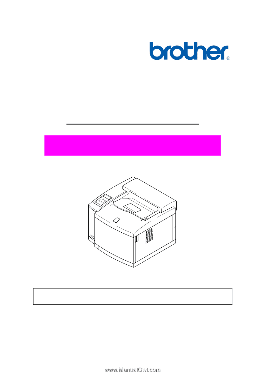
Brother Color Laser Printer
SERVICE MANUAL
MODEL: HL-2600CN
Read this manual thoroughly before maintenance work.
Keep this manual in a convenient place for quick and easy reference at all times.
October 2001
SM-PRN023