D-Link DGS-3426 User Manual - Page 106
IP-MAC-Port Binding, ACL Mode
 |
View all D-Link DGS-3426 manuals
Add to My Manuals
Save this manual to your list of manuals |
Page 106 highlights
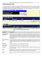
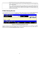
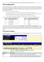
xStack DGS-3400 Series Layer 2 Gigabit Ethernet Managed Switch IP-MAC-Port Binding The IP network layer uses a four-byte address. The Ethernet link layer uses a six-byte MAC address. Binding these two address types together allows the transmission of data between the layers. The primary purpose of IP-MAC binding is to restrict the access to a switch to a number of authorized users. Only the authorized client can access the Switch's port by checking the pair of IPMAC addresses with the pre-configured database. If an unauthorized user tries to access an IP-MAC binding enabled port, the system will block the access by dropping its packet. The maximum number of IP-MAC binding entries is dependant on chip capability (e.g. the ARP table size) and storage size of the device. For the xStack DGS-3400 Series switches, the maximum number of IP-MAC Binding entries is 500. The creation of authorized users can be manually configured by CLI or Web. The function is port-based, meaning a user can enable or disable the function on the individual port. ACL Mode Due to some special cases that have arisen with the IP-MAC binding, this Switch has been equipped with a special ACL Mode for IP-MAC Binding, which should alleviate this problem for users. When enabled in the IPMAC Binding Port window, the Switch will create two entries in the Access Profile Table as shown below. The entries may only be created if there are at least two Access Profile IDs available on the Switch. If not, when the ACL Mode is enabled, an error message will be prompted to the user. When the ACL Mode is enabled, the Switch will only accept IP packets from a created entry in the IPMAC Binding Setting window. All others will be discarded. Figure 6- 64. Access Profile Table - IP-MAC-Port ACL Mode Enabled To view the particular configurations associated with these two entries, click their corresponding View button, which will display the following: Figure 6- 65. Access Profile Entry Display for IP-MAC ACL Mode Enabled Entries These two entries cannot be modified or deleted using the Access Profile Table. The user may only remove these two entries by disabling the ACL Mode in the IP-MAC Binding Port window. Also, rules will be created for every port on the Switch. To view the ACL rule configurations set for the ACL mode, click the corresponding modify button of the entry in the Access Profile Table, which will produce a window similar to the example to the right. The user may view the configurations on a port-by-port basis by clicking the View button under the Display heading of the corresponding port entry. These entries cannot be modified or deleted, and new rules cannot be added. Yet, these windows will offer vital information to the user when configuring other access profile entries. 92
-
 1
1 -
2
-
3
-
4
-
5
-
6
-
7
-
8
-
9
-
10
-
11
-
12
-
13
-
14
-
15
-
16
-
17
-
18
-
19
-
20
-
21
-
22
-
23
-
24
-
25
-
26
-
27
-
28
-
29
-
30
-
31
-
32
-
33
-
34
-
35
-
36
-
37
-
38
-
39
-
40
-
41
-
42
-
43
-
44
-
45
-
46
-
47
-
48
-
49
-
50
-
51
-
52
-
53
-
54
-
55
-
56
-
57
-
58
-
59
-
60
-
61
-
62
-
63
-
64
-
65
-
66
-
67
-
68
-
69
-
70
-
71
-
72
-
73
-
74
-
75
-
76
-
77
-
78
-
79
-
80
-
81
-
82
-
83
-
84
-
85
-
86
-
87
-
88
-
89
-
90
-
91
-
92
-
93
-
94
-
95
-
96
-
97
-
98
-
99
-
100
-
 101
101 -
 102
102 -
 103
103 -
 104
104 -
 105
105 -
 106
106 -
 107
107 -
 108
108 -
 109
109 -
 110
110 -
 111
111 -
112
-
113
-
114
-
115
-
116
-
117
-
118
-
119
-
120
-
121
-
122
-
123
-
124
-
125
-
126
-
127
-
128
-
129
-
130
-
131
-
132
-
133
-
134
-
135
-
136
-
137
-
138
-
139
-
140
-
141
-
142
-
143
-
144
-
145
-
146
-
147
-
148
-
149
-
150
-
151
-
152
-
153
-
154
-
155
-
156
-
157
-
158
-
159
-
160
-
161
-
162
-
163
-
164
-
165
-
166
-
167
-
168
-
169
-
170
-
171
-
172
-
173
-
174
-
175
-
176
-
177
-
178
-
179
-
180
-
181
-
182
-
183
-
184
-
185
-
186
-
187
-
188
-
189
-
190
-
191
-
192
-
193
-
194
-
195
-
196
-
197
-
198
-
199
-
200
-
201
-
202
-
203
-
204
-
205
-
206
-
207
-
208
-
209
-
210
-
211
-
212
-
213
-
214
-
215
-
216
-
217
-
218
-
219
-
220
-
221
-
222
-
223
-
224
-
225
-
226
-
227
-
228
-
229
-
230
-
231
-
232
-
233
-
234
-
235
-
236
-
237
-
238
-
239
-
240
-
241
-
242
-
243
-
244
-
245
-
246
-
247
-
248
-
249
-
250
-
251
-
252
-
253
-
254
-
255
-
256
-
257
-
258
-
259
-
260
-
261
-
262
-
263
-
264
-
265
-
266
-
267
-
268
-
269
-
270
-
271
-
272
-
273
-
274
-
275
-
276
-
277
-
278
-
279
-
280
-
281
-
282
-
283
-
284
-
285
-
286
-
287
-
288
-
289
-
290
-
291
-
292
-
293
-
294
-
295
-
296
-
297
-
298
-
299
-
300
-
301
-
302
-
303
-
304
-
305
-
306
-
307
-
308
-
309
-
310
-
311
-
312
-
313
-
314
-
315
-
316
-
317
-
318
-
319
-
320
-
321
-
322
-
323
-
324
-
325
-
326
-
327
-
328
-
329
-
330
-
331
-
332
-
333
-
334
-
335
-
336
-
337
-
338
-
339
-
340
-
341
-
342
-
343
-
344
-
345
-
346
-
347
-
348
-
349
-
350
-
351
-
352
-
353
-
354
-
355
-
356
 |
 |
