D-Link DGS-3426 User Manual - Page 71
System Log Save Mode Settings, System Log Save Mode Settings
 |
View all D-Link DGS-3426 manuals
Add to My Manuals
Save this manual to your list of manuals |
Page 71 highlights
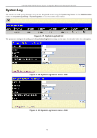
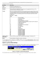
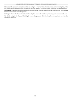
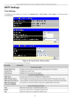
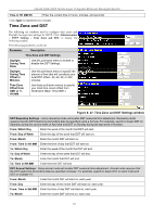
xStack DGS-3400 Series Layer 2 Gigabit Ethernet Managed Switch Configure the parameters listed below: Parameter Description Index Syslog server settings index (1-4). Server IP The IPv4 address of the Syslog server. Severity This drop-down menu allows you to select the level of messages that will be sent. The options are Warning, Informational, and All. Facility UDP Port (514 or 6000-65535) Some of the operating system daemons and processes have been assigned Facility values. Processes and daemons that have not been explicitly assigned a Facility may use any of the "local use" facilities or they may use the "user-level" Facility. Those Facilities that have been designated are shown in the following: Bold font means the facility values that the Switch currently now. Numerical Facility Code 0 kernel messages 1 user-level messages 2 mail system 3 system daemons 4 security/authorization messages 5 messages generated internally by syslog line printer subsystem 7 network news subsystem 8 UUCP subsystem 9 clock daemon 10 security/authorization messages 11 FTP daemon 12 NTP subsystem 13 log audit 14 log alert 15 clock daemon 16 local use 0 (local0) 17 local use 1 (local1) 18 local use 2 (local2) 19 local use 3 (local3) 20 local use 4 (local4) 21 local use 5 (local5) 22 local use 6 (local6) 23 local use 7 (local7) Type the UDP port number used for sending Syslog messages. The default is 514. Status Choose Enabled or Disabled to activate or deactivate. To set the System Log Server configuration, click Apply. To delete an entry from the System Log Server window, click the corresponding under the Delete heading of the entry to delete. To return to the Current System Log Servers window, click the Show All System Log Servers link. System Log Save Mode Settings The System Log Save Mode Settings window may be used to choose a method for which to save the switch log to the flash memory of the Switch. To view this window, click Administration > System Log > System Log Save Mode Settings. Figure 6- 24. System Log Save Mode Settings Use the pull-down menu to choose the method for saving the switch log to the Flash memory. The user has three options: 57
-
 1
1 -
2
-
3
-
4
-
5
-
6
-
7
-
8
-
9
-
10
-
11
-
12
-
13
-
14
-
15
-
16
-
17
-
18
-
19
-
20
-
21
-
22
-
23
-
24
-
25
-
26
-
27
-
28
-
29
-
30
-
31
-
32
-
33
-
34
-
35
-
36
-
37
-
38
-
39
-
40
-
41
-
42
-
43
-
44
-
45
-
46
-
47
-
48
-
49
-
50
-
51
-
52
-
53
-
54
-
55
-
56
-
57
-
58
-
59
-
60
-
61
-
62
-
63
-
64
-
65
-
 66
66 -
 67
67 -
 68
68 -
 69
69 -
 70
70 -
 71
71 -
 72
72 -
 73
73 -
 74
74 -
 75
75 -
 76
76 -
77
-
78
-
79
-
80
-
81
-
82
-
83
-
84
-
85
-
86
-
87
-
88
-
89
-
90
-
91
-
92
-
93
-
94
-
95
-
96
-
97
-
98
-
99
-
100
-
101
-
102
-
103
-
104
-
105
-
106
-
107
-
108
-
109
-
110
-
111
-
112
-
113
-
114
-
115
-
116
-
117
-
118
-
119
-
120
-
121
-
122
-
123
-
124
-
125
-
126
-
127
-
128
-
129
-
130
-
131
-
132
-
133
-
134
-
135
-
136
-
137
-
138
-
139
-
140
-
141
-
142
-
143
-
144
-
145
-
146
-
147
-
148
-
149
-
150
-
151
-
152
-
153
-
154
-
155
-
156
-
157
-
158
-
159
-
160
-
161
-
162
-
163
-
164
-
165
-
166
-
167
-
168
-
169
-
170
-
171
-
172
-
173
-
174
-
175
-
176
-
177
-
178
-
179
-
180
-
181
-
182
-
183
-
184
-
185
-
186
-
187
-
188
-
189
-
190
-
191
-
192
-
193
-
194
-
195
-
196
-
197
-
198
-
199
-
200
-
201
-
202
-
203
-
204
-
205
-
206
-
207
-
208
-
209
-
210
-
211
-
212
-
213
-
214
-
215
-
216
-
217
-
218
-
219
-
220
-
221
-
222
-
223
-
224
-
225
-
226
-
227
-
228
-
229
-
230
-
231
-
232
-
233
-
234
-
235
-
236
-
237
-
238
-
239
-
240
-
241
-
242
-
243
-
244
-
245
-
246
-
247
-
248
-
249
-
250
-
251
-
252
-
253
-
254
-
255
-
256
-
257
-
258
-
259
-
260
-
261
-
262
-
263
-
264
-
265
-
266
-
267
-
268
-
269
-
270
-
271
-
272
-
273
-
274
-
275
-
276
-
277
-
278
-
279
-
280
-
281
-
282
-
283
-
284
-
285
-
286
-
287
-
288
-
289
-
290
-
291
-
292
-
293
-
294
-
295
-
296
-
297
-
298
-
299
-
300
-
301
-
302
-
303
-
304
-
305
-
306
-
307
-
308
-
309
-
310
-
311
-
312
-
313
-
314
-
315
-
316
-
317
-
318
-
319
-
320
-
321
-
322
-
323
-
324
-
325
-
326
-
327
-
328
-
329
-
330
-
331
-
332
-
333
-
334
-
335
-
336
-
337
-
338
-
339
-
340
-
341
-
342
-
343
-
344
-
345
-
346
-
347
-
348
-
349
-
350
-
351
-
352
-
353
-
354
-
355
-
356
 |
 |
