D-Link DGS-3426 User Manual - Page 142
PVID Auto Assign, Double VLAN Configuration
 |
View all D-Link DGS-3426 manuals
Add to My Manuals
Save this manual to your list of manuals |
Page 142 highlights
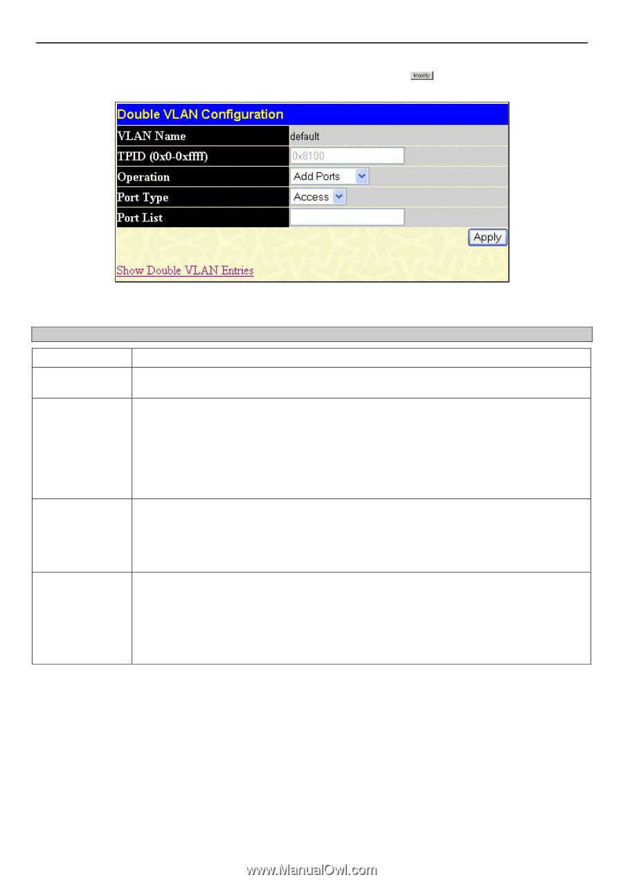
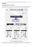
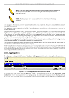
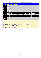
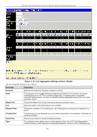
xStack DGS-3400 Series Layer 2 Gigabit Ethernet Managed Switch Click Apply to implement changes made. To configure the parameters for a previously created Service Provider VLAN, click the button of the corresponding SPVID in the Double VLAN Table as shown in Figure 7-10. The following window will appear for the user to configure. Figure 7- 13. Double VLAN Configuration To configure a Double VLAN, enter the following parameters and click Apply. Parameter Description VLAN Name TPID Operation Port Type Port List The name of the pre-configured VLAN name to be configured. The tagged protocol ID. Enter the new TPID in hex form to aid in packet identification of the Service Provider VLAN. Allows one of the following three acts to be performed: Add ports - Will allow users to add ports to this Service Provider VLAN using the Port List field below. Delete ports - Will allow users to remove ports from the Service Provider VLAN configured, using the Port List field below. Config TPID - Will allow users to configure the Tagged Protocol ID of the Service Provider VLAN, in hex form. Allows the user to choose the type of port being utilized by the Service Provider VLAN. The user may choose: Access - Access ports are for connecting Switch VLANs to customer VLANs. Uplink - Uplink ports are for connecting Switch VLANs to the Provider VLANs on a remote source. Use the From and To fields to set a list of ports to be placed in, or removed from, the Service Provider VLAN. The port list is specified by listing the lowest switch number and the beginning port number on that switch, separated by a colon. Then the highest switch number and the highest port number of the range (also separated by a colon) are specified. The beginning and end of the port list range are separated by a dash. For example, 1:3 specifies switch number 1, port 3. 2:4 specifies switch number 2, port 4. 1:3 - 2:4 specifies all of the ports between switch 1, port 3 and switch 2, port 4 − in numerical order. Entering all will denote all ports on the Switch. PVID Auto Assign To view this window, click L2 Features > VLAN > PVID Auto Assign. The following window will be displayed which will allow the user to enable or disable the PVID Auto Assign feature. 128
-
 1
1 -
2
-
3
-
4
-
5
-
6
-
7
-
8
-
9
-
10
-
11
-
12
-
13
-
14
-
15
-
16
-
17
-
18
-
19
-
20
-
21
-
22
-
23
-
24
-
25
-
26
-
27
-
28
-
29
-
30
-
31
-
32
-
33
-
34
-
35
-
36
-
37
-
38
-
39
-
40
-
41
-
42
-
43
-
44
-
45
-
46
-
47
-
48
-
49
-
50
-
51
-
52
-
53
-
54
-
55
-
56
-
57
-
58
-
59
-
60
-
61
-
62
-
63
-
64
-
65
-
66
-
67
-
68
-
69
-
70
-
71
-
72
-
73
-
74
-
75
-
76
-
77
-
78
-
79
-
80
-
81
-
82
-
83
-
84
-
85
-
86
-
87
-
88
-
89
-
90
-
91
-
92
-
93
-
94
-
95
-
96
-
97
-
98
-
99
-
100
-
101
-
102
-
103
-
104
-
105
-
106
-
107
-
108
-
109
-
110
-
111
-
112
-
113
-
114
-
115
-
116
-
117
-
118
-
119
-
120
-
121
-
122
-
123
-
124
-
125
-
126
-
127
-
128
-
129
-
130
-
131
-
132
-
133
-
134
-
135
-
136
-
 137
137 -
 138
138 -
 139
139 -
 140
140 -
 141
141 -
 142
142 -
 143
143 -
 144
144 -
 145
145 -
 146
146 -
 147
147 -
148
-
149
-
150
-
151
-
152
-
153
-
154
-
155
-
156
-
157
-
158
-
159
-
160
-
161
-
162
-
163
-
164
-
165
-
166
-
167
-
168
-
169
-
170
-
171
-
172
-
173
-
174
-
175
-
176
-
177
-
178
-
179
-
180
-
181
-
182
-
183
-
184
-
185
-
186
-
187
-
188
-
189
-
190
-
191
-
192
-
193
-
194
-
195
-
196
-
197
-
198
-
199
-
200
-
201
-
202
-
203
-
204
-
205
-
206
-
207
-
208
-
209
-
210
-
211
-
212
-
213
-
214
-
215
-
216
-
217
-
218
-
219
-
220
-
221
-
222
-
223
-
224
-
225
-
226
-
227
-
228
-
229
-
230
-
231
-
232
-
233
-
234
-
235
-
236
-
237
-
238
-
239
-
240
-
241
-
242
-
243
-
244
-
245
-
246
-
247
-
248
-
249
-
250
-
251
-
252
-
253
-
254
-
255
-
256
-
257
-
258
-
259
-
260
-
261
-
262
-
263
-
264
-
265
-
266
-
267
-
268
-
269
-
270
-
271
-
272
-
273
-
274
-
275
-
276
-
277
-
278
-
279
-
280
-
281
-
282
-
283
-
284
-
285
-
286
-
287
-
288
-
289
-
290
-
291
-
292
-
293
-
294
-
295
-
296
-
297
-
298
-
299
-
300
-
301
-
302
-
303
-
304
-
305
-
306
-
307
-
308
-
309
-
310
-
311
-
312
-
313
-
314
-
315
-
316
-
317
-
318
-
319
-
320
-
321
-
322
-
323
-
324
-
325
-
326
-
327
-
328
-
329
-
330
-
331
-
332
-
333
-
334
-
335
-
336
-
337
-
338
-
339
-
340
-
341
-
342
-
343
-
344
-
345
-
346
-
347
-
348
-
349
-
350
-
351
-
352
-
353
-
354
-
355
-
356
 |
 |