D-Link DGS-3426 User Manual - Page 203
CPU Interface Filtering, CPU Interface Filtering State Settings window
 |
View all D-Link DGS-3426 manuals
Add to My Manuals
Save this manual to your list of manuals |
Page 203 highlights
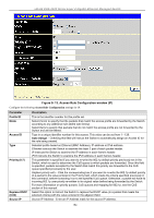
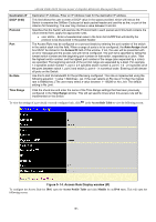
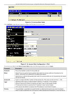
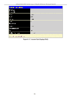
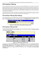
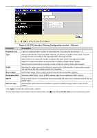
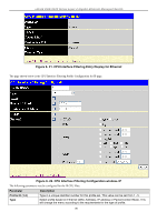
xStack DGS-3400 Series Layer 2 Gigabit Ethernet Managed Switch CPU Interface Filtering Due to a chipset limitation and needed extra switch security, the xStack DGS-3400 Series switch incorporates CPU Interface filtering. This added feature increases the running security of the Switch by enabling the user to create a list of access rules for packets destined for the Switch's CPU interface. Employed similarly to the Access Profile feature previously mentioned, CPU interface filtering examines Ethernet, IP and Packet Content Mask packet headers destined for the CPU and will either forward them or filter them, based on the user's implementation. As an added feature for the CPU Filtering, the xStack DGS-3400 Series switch allows the CPU filtering mechanism to be enabled or disabled globally, permitting the user to create various lists of rules without immediately enabling them. Creating an access profile for the CPU is divided into two basic parts. The first is to specify which part or parts of a frame the Switch will examine, such as the MAC source address or the IP destination address. The second part is entering the criteria the Switch will use to determine what to do with the frame. The entire process is described below. CPU Interface Filtering State Settings In the following window, the user may globally enable or disable the CPU Interface Filtering mechanism by using the pull-down menu to change the running state. To access this window, click ACL > CPU Interface Filtering > CPU Interface Filtering State. Choose Enabled to enable CPU packets to be scrutinized by the Switch and Disabled to disallow this scrutiny. Figure 9- 18. CPU Interface Filtering State Settings window CPU Interface Filtering Table The CPU Interface Filtering Table displays the CPU Access Profile Table entries created on the Switch. To view the configurations for an entry, click the hyperlinked Profile ID number. To view this window click ACL > CPU Interface Filtering > CPU Interface Filtering Table. Figure 9- 19. CPU Interface Filtering Table To add an entry to the CPU Interface Filtering Table, click the Add Profile button. This will open the CPU Interface Filtering Configuration page, as shown below. To remove all CPU Interface Filtering Table entries, click the Clear All button. There are three Access Profile Configuration pages; one for Ethernet (or MAC address-based) profile configuration, one for IP addressbased profile configuration and one for the Packet Content Mask. You can switch between the three Access Profile Configuration pages by using the Type drop-down menu. The page shown below is the Ethernet CPU Interface Filtering Configuration page. 189
-
 1
1 -
2
-
3
-
4
-
5
-
6
-
7
-
8
-
9
-
10
-
11
-
12
-
13
-
14
-
15
-
16
-
17
-
18
-
19
-
20
-
21
-
22
-
23
-
24
-
25
-
26
-
27
-
28
-
29
-
30
-
31
-
32
-
33
-
34
-
35
-
36
-
37
-
38
-
39
-
40
-
41
-
42
-
43
-
44
-
45
-
46
-
47
-
48
-
49
-
50
-
51
-
52
-
53
-
54
-
55
-
56
-
57
-
58
-
59
-
60
-
61
-
62
-
63
-
64
-
65
-
66
-
67
-
68
-
69
-
70
-
71
-
72
-
73
-
74
-
75
-
76
-
77
-
78
-
79
-
80
-
81
-
82
-
83
-
84
-
85
-
86
-
87
-
88
-
89
-
90
-
91
-
92
-
93
-
94
-
95
-
96
-
97
-
98
-
99
-
100
-
101
-
102
-
103
-
104
-
105
-
106
-
107
-
108
-
109
-
110
-
111
-
112
-
113
-
114
-
115
-
116
-
117
-
118
-
119
-
120
-
121
-
122
-
123
-
124
-
125
-
126
-
127
-
128
-
129
-
130
-
131
-
132
-
133
-
134
-
135
-
136
-
137
-
138
-
139
-
140
-
141
-
142
-
143
-
144
-
145
-
146
-
147
-
148
-
149
-
150
-
151
-
152
-
153
-
154
-
155
-
156
-
157
-
158
-
159
-
160
-
161
-
162
-
163
-
164
-
165
-
166
-
167
-
168
-
169
-
170
-
171
-
172
-
173
-
174
-
175
-
176
-
177
-
178
-
179
-
180
-
181
-
182
-
183
-
184
-
185
-
186
-
187
-
188
-
189
-
190
-
191
-
192
-
193
-
194
-
195
-
196
-
197
-
 198
198 -
 199
199 -
 200
200 -
 201
201 -
 202
202 -
 203
203 -
 204
204 -
 205
205 -
 206
206 -
 207
207 -
 208
208 -
209
-
210
-
211
-
212
-
213
-
214
-
215
-
216
-
217
-
218
-
219
-
220
-
221
-
222
-
223
-
224
-
225
-
226
-
227
-
228
-
229
-
230
-
231
-
232
-
233
-
234
-
235
-
236
-
237
-
238
-
239
-
240
-
241
-
242
-
243
-
244
-
245
-
246
-
247
-
248
-
249
-
250
-
251
-
252
-
253
-
254
-
255
-
256
-
257
-
258
-
259
-
260
-
261
-
262
-
263
-
264
-
265
-
266
-
267
-
268
-
269
-
270
-
271
-
272
-
273
-
274
-
275
-
276
-
277
-
278
-
279
-
280
-
281
-
282
-
283
-
284
-
285
-
286
-
287
-
288
-
289
-
290
-
291
-
292
-
293
-
294
-
295
-
296
-
297
-
298
-
299
-
300
-
301
-
302
-
303
-
304
-
305
-
306
-
307
-
308
-
309
-
310
-
311
-
312
-
313
-
314
-
315
-
316
-
317
-
318
-
319
-
320
-
321
-
322
-
323
-
324
-
325
-
326
-
327
-
328
-
329
-
330
-
331
-
332
-
333
-
334
-
335
-
336
-
337
-
338
-
339
-
340
-
341
-
342
-
343
-
344
-
345
-
346
-
347
-
348
-
349
-
350
-
351
-
352
-
353
-
354
-
355
-
356
 |
 |
