D-Link DGS-3426 User Manual - Page 62
Stacking Mode Settings, Box Information, Stacking Mode Settings window
 |
View all D-Link DGS-3426 manuals
Add to My Manuals
Save this manual to your list of manuals |
Page 62 highlights
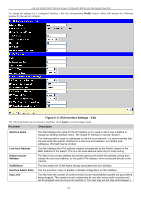
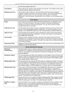
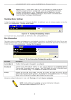
xStack DGS-3400 Series Layer 2 Gigabit Ethernet Managed Switch NOTE: If there is a Box ID conflict when the stack is in the discovery phase, the device will enter a special standalone topology mode. Users can only get device information, configure Box IDs, save and reboot. All stacking ports will be disabled and an error message will be produced on the local console port of each device in the stack. Users must reconfigure Box IDs and reboot the stack. Stacking Mode Settings To begin the stacking process, users must first enable this device for stacking by using the following window. To view this window, click Administration > Stacking > Mode Settings. Figure 6- 11. Stacking Mode Settings window Use the pull-down menu, choose Enabled and click Apply to allow stacking of this Switch. Box Information This window is used to configure stacking parameters associated with all switches in the xStack DGS-3400 Series. The user may configure parameters such as box ID, box priority and pre-assigning model names to switches to be entered into the switch stack. To view this window click Administration > Stacking > Box Information. Parameter Current Box ID Figure 6- 12. Box Information Configuration window Description The Box ID of the switch in the stack to be configured. New Box ID The new box ID of the selected switch in the stack that was selected in the Current Box ID field. The user may choose any number between 1 and 12 to identify the switch in the switch stack. Auto will automatically assign a box number to the switch in the switch stack. Priority Displays the priority ID of the Switch. The lower the number, the higher the priority. The box (switch) with the lowest priority number in the stack is the Primary Master switch. The Primary Master switch will be used to configure applications of the switch stack. Information configured in this screen is found in the Monitoring folder under Stacking Information. NOTE: Configured box priority settings will not be implemented until users physically save it using the Web GUI or the CLI. 48
-
 1
1 -
2
-
3
-
4
-
5
-
6
-
7
-
8
-
9
-
10
-
11
-
12
-
13
-
14
-
15
-
16
-
17
-
18
-
19
-
20
-
21
-
22
-
23
-
24
-
25
-
26
-
27
-
28
-
29
-
30
-
31
-
32
-
33
-
34
-
35
-
36
-
37
-
38
-
39
-
40
-
41
-
42
-
43
-
44
-
45
-
46
-
47
-
48
-
49
-
50
-
51
-
52
-
53
-
54
-
55
-
56
-
 57
57 -
 58
58 -
 59
59 -
 60
60 -
 61
61 -
 62
62 -
 63
63 -
 64
64 -
 65
65 -
 66
66 -
 67
67 -
68
-
69
-
70
-
71
-
72
-
73
-
74
-
75
-
76
-
77
-
78
-
79
-
80
-
81
-
82
-
83
-
84
-
85
-
86
-
87
-
88
-
89
-
90
-
91
-
92
-
93
-
94
-
95
-
96
-
97
-
98
-
99
-
100
-
101
-
102
-
103
-
104
-
105
-
106
-
107
-
108
-
109
-
110
-
111
-
112
-
113
-
114
-
115
-
116
-
117
-
118
-
119
-
120
-
121
-
122
-
123
-
124
-
125
-
126
-
127
-
128
-
129
-
130
-
131
-
132
-
133
-
134
-
135
-
136
-
137
-
138
-
139
-
140
-
141
-
142
-
143
-
144
-
145
-
146
-
147
-
148
-
149
-
150
-
151
-
152
-
153
-
154
-
155
-
156
-
157
-
158
-
159
-
160
-
161
-
162
-
163
-
164
-
165
-
166
-
167
-
168
-
169
-
170
-
171
-
172
-
173
-
174
-
175
-
176
-
177
-
178
-
179
-
180
-
181
-
182
-
183
-
184
-
185
-
186
-
187
-
188
-
189
-
190
-
191
-
192
-
193
-
194
-
195
-
196
-
197
-
198
-
199
-
200
-
201
-
202
-
203
-
204
-
205
-
206
-
207
-
208
-
209
-
210
-
211
-
212
-
213
-
214
-
215
-
216
-
217
-
218
-
219
-
220
-
221
-
222
-
223
-
224
-
225
-
226
-
227
-
228
-
229
-
230
-
231
-
232
-
233
-
234
-
235
-
236
-
237
-
238
-
239
-
240
-
241
-
242
-
243
-
244
-
245
-
246
-
247
-
248
-
249
-
250
-
251
-
252
-
253
-
254
-
255
-
256
-
257
-
258
-
259
-
260
-
261
-
262
-
263
-
264
-
265
-
266
-
267
-
268
-
269
-
270
-
271
-
272
-
273
-
274
-
275
-
276
-
277
-
278
-
279
-
280
-
281
-
282
-
283
-
284
-
285
-
286
-
287
-
288
-
289
-
290
-
291
-
292
-
293
-
294
-
295
-
296
-
297
-
298
-
299
-
300
-
301
-
302
-
303
-
304
-
305
-
306
-
307
-
308
-
309
-
310
-
311
-
312
-
313
-
314
-
315
-
316
-
317
-
318
-
319
-
320
-
321
-
322
-
323
-
324
-
325
-
326
-
327
-
328
-
329
-
330
-
331
-
332
-
333
-
334
-
335
-
336
-
337
-
338
-
339
-
340
-
341
-
342
-
343
-
344
-
345
-
346
-
347
-
348
-
349
-
350
-
351
-
352
-
353
-
354
-
355
-
356
 |
 |
