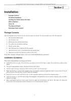
D-Link DGS-3426 User Manual - Page 20
Power, Console, Port LEDs, 10GE Ports, Combo SFP Ports, Stack ID, Link/Act/Speed - dgs 3426p
 |
View all D-Link DGS-3426 manuals
Add to My Manuals
Save this manual to your list of manuals |
Page 20 highlights
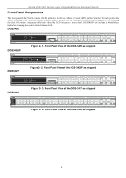
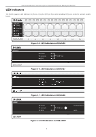
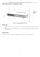
xStack DGS-3400 Series Layer 2 Gigabit Ethernet Managed Switch LED Power Description This LED will light green after powering the Switch on to indicate the ready state of the device. The indicator is dark when the Switch is no longer receiving power (i.e powered off). Console This LED will blink green during the Power-On Self Test (POST). When the POST is finished, the LED goes dark. The indicator will light steady green when an active console link is in session via RS-232 console port. RPS This LED will light when the internal power has failed and the RPS has taken over the power supply to the Switch. Otherwise, it will remain dark. Port LEDs One row of LEDs for each port is located above the ports on the front panel. The indicator above the left side of a port corresponds to the port below the indicator in the upper row of ports. The indicator above the right side of a port corresponds to the port below the indicator in the lower row of ports. A steady green light denotes a valid 1000Mbps link on the port while a blinking green light indicates activity on the port (at 1000Mbps). A steady orange light denotes a valid 10 or 100Mbps link on the port while a blinking orange light indicates activity on the port (at 100Mbps). These LEDs will remain dark if there is no link/activity on the port. 10GE Ports A steady green light denotes a valid link on the port while a blinking green light indicates activity on the port. These LEDs will remain dark if there is no link/activity on the port. Combo SFP Ports LED indicators for the Combo ports are located above the ports and numbered 1 - 4 for Combo 1, Combo 2, etc. ports. A steady green light denotes a valid link on the port while a blinking green light indicates activity on the port. These LEDs will remain dark if there is no link/activity on the port. Stack ID These two seven segment LEDs display the current switch stack order of the Switch while in use. Link/Act/Speed and PoE (DGS-3426P only) To change the LED mode from Link/Act/Speed to PoE and vice versa, press the LED Mode Select Button. The Link/Act/Speed LED will light solid green when selected and will shut off when PoE is selected. Likewise, when Link/Act/Speed is selected, the PoE LED shuts off and the Link/Act/Speed LED lights solid green. 6
-
 1
1 -
2
-
3
-
4
-
5
-
6
-
7
-
8
-
9
-
10
-
11
-
12
-
13
-
14
-
 15
15 -
 16
16 -
 17
17 -
 18
18 -
 19
19 -
 20
20 -
 21
21 -
 22
22 -
 23
23 -
 24
24 -
 25
25 -
26
-
27
-
28
-
29
-
30
-
31
-
32
-
33
-
34
-
35
-
36
-
37
-
38
-
39
-
40
-
41
-
42
-
43
-
44
-
45
-
46
-
47
-
48
-
49
-
50
-
51
-
52
-
53
-
54
-
55
-
56
-
57
-
58
-
59
-
60
-
61
-
62
-
63
-
64
-
65
-
66
-
67
-
68
-
69
-
70
-
71
-
72
-
73
-
74
-
75
-
76
-
77
-
78
-
79
-
80
-
81
-
82
-
83
-
84
-
85
-
86
-
87
-
88
-
89
-
90
-
91
-
92
-
93
-
94
-
95
-
96
-
97
-
98
-
99
-
100
-
101
-
102
-
103
-
104
-
105
-
106
-
107
-
108
-
109
-
110
-
111
-
112
-
113
-
114
-
115
-
116
-
117
-
118
-
119
-
120
-
121
-
122
-
123
-
124
-
125
-
126
-
127
-
128
-
129
-
130
-
131
-
132
-
133
-
134
-
135
-
136
-
137
-
138
-
139
-
140
-
141
-
142
-
143
-
144
-
145
-
146
-
147
-
148
-
149
-
150
-
151
-
152
-
153
-
154
-
155
-
156
-
157
-
158
-
159
-
160
-
161
-
162
-
163
-
164
-
165
-
166
-
167
-
168
-
169
-
170
-
171
-
172
-
173
-
174
-
175
-
176
-
177
-
178
-
179
-
180
-
181
-
182
-
183
-
184
-
185
-
186
-
187
-
188
-
189
-
190
-
191
-
192
-
193
-
194
-
195
-
196
-
197
-
198
-
199
-
200
-
201
-
202
-
203
-
204
-
205
-
206
-
207
-
208
-
209
-
210
-
211
-
212
-
213
-
214
-
215
-
216
-
217
-
218
-
219
-
220
-
221
-
222
-
223
-
224
-
225
-
226
-
227
-
228
-
229
-
230
-
231
-
232
-
233
-
234
-
235
-
236
-
237
-
238
-
239
-
240
-
241
-
242
-
243
-
244
-
245
-
246
-
247
-
248
-
249
-
250
-
251
-
252
-
253
-
254
-
255
-
256
-
257
-
258
-
259
-
260
-
261
-
262
-
263
-
264
-
265
-
266
-
267
-
268
-
269
-
270
-
271
-
272
-
273
-
274
-
275
-
276
-
277
-
278
-
279
-
280
-
281
-
282
-
283
-
284
-
285
-
286
-
287
-
288
-
289
-
290
-
291
-
292
-
293
-
294
-
295
-
296
-
297
-
298
-
299
-
300
-
301
-
302
-
303
-
304
-
305
-
306
-
307
-
308
-
309
-
310
-
311
-
312
-
313
-
314
-
315
-
316
-
317
-
318
-
319
-
320
-
321
-
322
-
323
-
324
-
325
-
326
-
327
-
328
-
329
-
330
-
331
-
332
-
333
-
334
-
335
-
336
-
337
-
338
-
339
-
340
-
341
-
342
-
343
-
344
-
345
-
346
-
347
-
348
-
349
-
350
-
351
-
352
-
353
-
354
-
355
-
356
 |
 |