D-Link DGS-3426 User Manual - Page 198
Access Rule Configuration window IP, Parameter, Description, Profile ID, Access ID
 |
View all D-Link DGS-3426 manuals
Add to My Manuals
Save this manual to your list of manuals |
Page 198 highlights
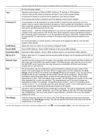
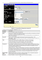
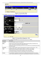
xStack DGS-3400 Series Layer 2 Gigabit Ethernet Managed Switch Figure 9- 13. Access Rule Configuration window (IP) Configure the following Access Rule Configuration settings for IP: Parameter Description Profile ID Mode Access ID Type Priority (0-7) Replace DSCP (0-63) Source IP This is the identifier number for this profile set. Select Permit to specify that the packets that match the access profile are forwarded by the Switch, according to any additional rule added (see below). Select Deny to specify that packets that do not match the access profile are not forwarded by the Switch and will be filtered. Type in a unique identifier number for this access. This value can be set from 1 - 128. Auto Assign - Checking this field will instruct the Switch to automatically assign an Access ID for the rule being created. Selected profile based on Ethernet (MAC Address), IP address or IPv6 address. Ethernet instructs the Switch to examine the layer 2 part of each packet header. IP instructs the Switch to examine the IP address in each frame's header. IPv6 instructs the Switch to examine the IPv6 address in each frame's header. This parameter is specified if you want to re-write the 802.1p default priority previously set in the Switch, which is used to determine the CoS queue to which packets are forwarded. Once this field is specified, packets accepted by the Switch that match this priority are forwarded to the CoS queue specified previously by the user. Replace priority with − Click the corresponding box if you want to re-write the 802.1p default priority of a packet to the value entered in the Priority field, which meets the criteria specified previously in this command, before forwarding it on to the specified CoS queue. Otherwise, a packet will have its incoming 802.1p user priority re-written to its original value before being forwarded by the Switch. For more information on priority queues, CoS queues and mapping for 802.1p, see the QoS section of this manual. Select this option to instruct the Switch to replace the DSCP value (in a packet that meets the selected criteria) with the value entered in the adjacent field. Source IP Address - Enter an IP Address mask for the source IP address. 184
-
 1
1 -
2
-
3
-
4
-
5
-
6
-
7
-
8
-
9
-
10
-
11
-
12
-
13
-
14
-
15
-
16
-
17
-
18
-
19
-
20
-
21
-
22
-
23
-
24
-
25
-
26
-
27
-
28
-
29
-
30
-
31
-
32
-
33
-
34
-
35
-
36
-
37
-
38
-
39
-
40
-
41
-
42
-
43
-
44
-
45
-
46
-
47
-
48
-
49
-
50
-
51
-
52
-
53
-
54
-
55
-
56
-
57
-
58
-
59
-
60
-
61
-
62
-
63
-
64
-
65
-
66
-
67
-
68
-
69
-
70
-
71
-
72
-
73
-
74
-
75
-
76
-
77
-
78
-
79
-
80
-
81
-
82
-
83
-
84
-
85
-
86
-
87
-
88
-
89
-
90
-
91
-
92
-
93
-
94
-
95
-
96
-
97
-
98
-
99
-
100
-
101
-
102
-
103
-
104
-
105
-
106
-
107
-
108
-
109
-
110
-
111
-
112
-
113
-
114
-
115
-
116
-
117
-
118
-
119
-
120
-
121
-
122
-
123
-
124
-
125
-
126
-
127
-
128
-
129
-
130
-
131
-
132
-
133
-
134
-
135
-
136
-
137
-
138
-
139
-
140
-
141
-
142
-
143
-
144
-
145
-
146
-
147
-
148
-
149
-
150
-
151
-
152
-
153
-
154
-
155
-
156
-
157
-
158
-
159
-
160
-
161
-
162
-
163
-
164
-
165
-
166
-
167
-
168
-
169
-
170
-
171
-
172
-
173
-
174
-
175
-
176
-
177
-
178
-
179
-
180
-
181
-
182
-
183
-
184
-
185
-
186
-
187
-
188
-
189
-
190
-
191
-
192
-
 193
193 -
 194
194 -
 195
195 -
 196
196 -
 197
197 -
 198
198 -
 199
199 -
 200
200 -
 201
201 -
 202
202 -
 203
203 -
204
-
205
-
206
-
207
-
208
-
209
-
210
-
211
-
212
-
213
-
214
-
215
-
216
-
217
-
218
-
219
-
220
-
221
-
222
-
223
-
224
-
225
-
226
-
227
-
228
-
229
-
230
-
231
-
232
-
233
-
234
-
235
-
236
-
237
-
238
-
239
-
240
-
241
-
242
-
243
-
244
-
245
-
246
-
247
-
248
-
249
-
250
-
251
-
252
-
253
-
254
-
255
-
256
-
257
-
258
-
259
-
260
-
261
-
262
-
263
-
264
-
265
-
266
-
267
-
268
-
269
-
270
-
271
-
272
-
273
-
274
-
275
-
276
-
277
-
278
-
279
-
280
-
281
-
282
-
283
-
284
-
285
-
286
-
287
-
288
-
289
-
290
-
291
-
292
-
293
-
294
-
295
-
296
-
297
-
298
-
299
-
300
-
301
-
302
-
303
-
304
-
305
-
306
-
307
-
308
-
309
-
310
-
311
-
312
-
313
-
314
-
315
-
316
-
317
-
318
-
319
-
320
-
321
-
322
-
323
-
324
-
325
-
326
-
327
-
328
-
329
-
330
-
331
-
332
-
333
-
334
-
335
-
336
-
337
-
338
-
339
-
340
-
341
-
342
-
343
-
344
-
345
-
346
-
347
-
348
-
349
-
350
-
351
-
352
-
353
-
354
-
355
-
356
 |
 |
