D-Link DGS-3426 User Manual - Page 111
PoE Configuration, PoE System Settings, PoE System Settings and Information window
 |
View all D-Link DGS-3426 manuals
Add to My Manuals
Save this manual to your list of manuals |
Page 111 highlights
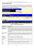
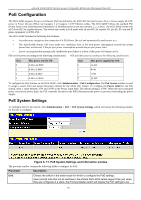
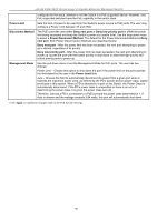
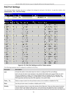
xStack DGS-3400 Series Layer 2 Gigabit Ethernet Managed Switch PoE Configuration The DGS-3426P supports Power over Ethernet (PoE) as defined by the IEEE 802.3af specification. Ports 1-24 can supply 48 VDC power to Power Devices (PDs) over Category 5 or Category 3 UTP Ethernet cables. The DGS-3426P follows the standard PSE (Power Source over Ethernet) pinout Alternative A, whereby power is sent out over pins 1, 2, 3 and 6. The DGS-3426P works with all D-Link 802.3af capable devices. The Switch also works in PoE mode with all non-802.3af capable D-Link AP, IP Cam and IP phone equipment via DWL-P50. The DGS-3426P includes the following PoE features: • Auto-discovery recognizes the connection of a PD (Power Device) and automatically sends power to it. • The Auto-disable feature will occur under two conditions: first, if the total power consumption exceeds the system power limit; and second, if the per port power consumption exceeds the per port power limit. • Active circuit protection automatically disables the port if there is a short. Other ports will remain active. PDs receive power according to the following classification: PSE provides power according to the following classification: Class 0 1 2 3 Max power used by PD 0.44 to 12.95W 0.44 to 3.84W 3.84 to 6.49W 6.49 to 12.95W Class 0 1 2 3 Max power supplied by PSE 15.4W 4.0W 7.0W 15.4W To configure the PoE features on the DGS-3426P, click Administration > PoE Configuration. The PoE System window is used to assign a power limit and power disconnect method for the whole PoE system. To configure the Power Limit for the PoE system, enter a value between 37W and 370W in the Power Limit field. The default setting is 370W. When the total consumed power exceeds the power limit, the PoE controller (located in the PSE) disconnects the power to prevent overloading the power supply. PoE System Settings To configure PoE for the Switch, click Administration > PoE > PoE System Settings, which will reveal the following window for the user to configure: Figure 6- 71. PoE System Settings and Information window The previous window contains the following fields to configure for PoE: Parameter Description Unit Choose the switch in the switch stack for which to configure the PoE settings. Users should note that not all switches in the xStack DGS-3400 series support PoE yet, when they are configured in a stack, the Primary Master switch will display the PoE settings to be 97
-
 1
1 -
2
-
3
-
4
-
5
-
6
-
7
-
8
-
9
-
10
-
11
-
12
-
13
-
14
-
15
-
16
-
17
-
18
-
19
-
20
-
21
-
22
-
23
-
24
-
25
-
26
-
27
-
28
-
29
-
30
-
31
-
32
-
33
-
34
-
35
-
36
-
37
-
38
-
39
-
40
-
41
-
42
-
43
-
44
-
45
-
46
-
47
-
48
-
49
-
50
-
51
-
52
-
53
-
54
-
55
-
56
-
57
-
58
-
59
-
60
-
61
-
62
-
63
-
64
-
65
-
66
-
67
-
68
-
69
-
70
-
71
-
72
-
73
-
74
-
75
-
76
-
77
-
78
-
79
-
80
-
81
-
82
-
83
-
84
-
85
-
86
-
87
-
88
-
89
-
90
-
91
-
92
-
93
-
94
-
95
-
96
-
97
-
98
-
99
-
100
-
101
-
102
-
103
-
104
-
105
-
 106
106 -
 107
107 -
 108
108 -
 109
109 -
 110
110 -
 111
111 -
 112
112 -
 113
113 -
 114
114 -
 115
115 -
 116
116 -
117
-
118
-
119
-
120
-
121
-
122
-
123
-
124
-
125
-
126
-
127
-
128
-
129
-
130
-
131
-
132
-
133
-
134
-
135
-
136
-
137
-
138
-
139
-
140
-
141
-
142
-
143
-
144
-
145
-
146
-
147
-
148
-
149
-
150
-
151
-
152
-
153
-
154
-
155
-
156
-
157
-
158
-
159
-
160
-
161
-
162
-
163
-
164
-
165
-
166
-
167
-
168
-
169
-
170
-
171
-
172
-
173
-
174
-
175
-
176
-
177
-
178
-
179
-
180
-
181
-
182
-
183
-
184
-
185
-
186
-
187
-
188
-
189
-
190
-
191
-
192
-
193
-
194
-
195
-
196
-
197
-
198
-
199
-
200
-
201
-
202
-
203
-
204
-
205
-
206
-
207
-
208
-
209
-
210
-
211
-
212
-
213
-
214
-
215
-
216
-
217
-
218
-
219
-
220
-
221
-
222
-
223
-
224
-
225
-
226
-
227
-
228
-
229
-
230
-
231
-
232
-
233
-
234
-
235
-
236
-
237
-
238
-
239
-
240
-
241
-
242
-
243
-
244
-
245
-
246
-
247
-
248
-
249
-
250
-
251
-
252
-
253
-
254
-
255
-
256
-
257
-
258
-
259
-
260
-
261
-
262
-
263
-
264
-
265
-
266
-
267
-
268
-
269
-
270
-
271
-
272
-
273
-
274
-
275
-
276
-
277
-
278
-
279
-
280
-
281
-
282
-
283
-
284
-
285
-
286
-
287
-
288
-
289
-
290
-
291
-
292
-
293
-
294
-
295
-
296
-
297
-
298
-
299
-
300
-
301
-
302
-
303
-
304
-
305
-
306
-
307
-
308
-
309
-
310
-
311
-
312
-
313
-
314
-
315
-
316
-
317
-
318
-
319
-
320
-
321
-
322
-
323
-
324
-
325
-
326
-
327
-
328
-
329
-
330
-
331
-
332
-
333
-
334
-
335
-
336
-
337
-
338
-
339
-
340
-
341
-
342
-
343
-
344
-
345
-
346
-
347
-
348
-
349
-
350
-
351
-
352
-
353
-
354
-
355
-
356
 |
 |
