D-Link DGS-3426 User Manual - Page 154
ISM VLAN, Restrictions and Provisos
 |
View all D-Link DGS-3426 manuals
Add to My Manuals
Save this manual to your list of manuals |
Page 154 highlights
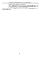
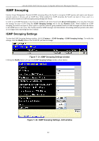
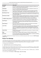
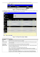
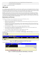
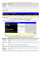
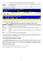
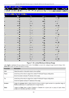
xStack DGS-3400 Series Layer 2 Gigabit Ethernet Managed Switch ports will not send out routing packets Click Apply to implement the new settings. ISM VLAN In a switching environment, multiple VLANs may exist. Every time a multicast query passes through the Switch, the switch must forward separate different copies of the data to each VLAN on the system, which, in turn, increases data traffic and may clog up the traffic path. To lighten the traffic load, multicast VLANs may be incorporated. These multicast VLANs will allow the Switch to forward this multicast traffic as one copy to recipients of the multicast VLAN, instead of multiple copies. Regardless of other normal VLANs that are incorporated on the Switch, users may add any ports to the multicast VLAN where they wish multicast traffic to be sent. Users are to set up a source port, where the multicast traffic is entering the switch, and then set the ports where the incoming multicast traffic is to be sent. The source port cannot be a recipient port and if configured to do so, will cause error messages to be produced by the switch. Once properly configured, the stream of multicast data will be relayed to the receiver ports in a much more timely and reliable fashion. Restrictions and Provisos The Multicast VLAN feature of this switch does have some restrictions and limitations, such as: 1. Multicast VLANs can only be implemented on edge switches. 2. Member ports and source ports can be used in multiple ISM VLANs. But member ports and source ports cannot be the same port in a specific ISM VLAN. 3. The Multicast VLAN is exclusive with normal 802.1q VLANs, which means that VLAN IDs (VIDs) and VLAN Names of 802.1q VLANs and ISM VLANs cannot be the same. Once a VID or VLAN Name is chosen for any VLAN, it cannot be used for any other VLAN. 4. The normal display of configured VLANs will not display configured Multicast VLANs. 5. Once an ISM VLAN is enabled, the corresponding IGMP snooping state of this VLAN will also be enabled. Users cannot disable the IGMP feature for an enabled ISM VLAN. 6. User can configure 16 ranges of multicast groups, no upper limitation of each range. 7. Router ports cannot be deleted if they are the source ports for ISM VLANs. To configure the ISM Vlan Settings window, click L2 Features > IGMP Snooping > ISM VLAN Settings, which will open the following window: Figure 7- 25. IGMP Snooping Multicast VLAN Table window Clicking the Add button will reveal the following window to configure: Figure 7- 26. IGMP Snooping Multicast VLAN Settings - Add window 140
-
 1
1 -
2
-
3
-
4
-
5
-
6
-
7
-
8
-
9
-
10
-
11
-
12
-
13
-
14
-
15
-
16
-
17
-
18
-
19
-
20
-
21
-
22
-
23
-
24
-
25
-
26
-
27
-
28
-
29
-
30
-
31
-
32
-
33
-
34
-
35
-
36
-
37
-
38
-
39
-
40
-
41
-
42
-
43
-
44
-
45
-
46
-
47
-
48
-
49
-
50
-
51
-
52
-
53
-
54
-
55
-
56
-
57
-
58
-
59
-
60
-
61
-
62
-
63
-
64
-
65
-
66
-
67
-
68
-
69
-
70
-
71
-
72
-
73
-
74
-
75
-
76
-
77
-
78
-
79
-
80
-
81
-
82
-
83
-
84
-
85
-
86
-
87
-
88
-
89
-
90
-
91
-
92
-
93
-
94
-
95
-
96
-
97
-
98
-
99
-
100
-
101
-
102
-
103
-
104
-
105
-
106
-
107
-
108
-
109
-
110
-
111
-
112
-
113
-
114
-
115
-
116
-
117
-
118
-
119
-
120
-
121
-
122
-
123
-
124
-
125
-
126
-
127
-
128
-
129
-
130
-
131
-
132
-
133
-
134
-
135
-
136
-
137
-
138
-
139
-
140
-
141
-
142
-
143
-
144
-
145
-
146
-
147
-
148
-
 149
149 -
 150
150 -
 151
151 -
 152
152 -
 153
153 -
 154
154 -
 155
155 -
 156
156 -
 157
157 -
 158
158 -
 159
159 -
160
-
161
-
162
-
163
-
164
-
165
-
166
-
167
-
168
-
169
-
170
-
171
-
172
-
173
-
174
-
175
-
176
-
177
-
178
-
179
-
180
-
181
-
182
-
183
-
184
-
185
-
186
-
187
-
188
-
189
-
190
-
191
-
192
-
193
-
194
-
195
-
196
-
197
-
198
-
199
-
200
-
201
-
202
-
203
-
204
-
205
-
206
-
207
-
208
-
209
-
210
-
211
-
212
-
213
-
214
-
215
-
216
-
217
-
218
-
219
-
220
-
221
-
222
-
223
-
224
-
225
-
226
-
227
-
228
-
229
-
230
-
231
-
232
-
233
-
234
-
235
-
236
-
237
-
238
-
239
-
240
-
241
-
242
-
243
-
244
-
245
-
246
-
247
-
248
-
249
-
250
-
251
-
252
-
253
-
254
-
255
-
256
-
257
-
258
-
259
-
260
-
261
-
262
-
263
-
264
-
265
-
266
-
267
-
268
-
269
-
270
-
271
-
272
-
273
-
274
-
275
-
276
-
277
-
278
-
279
-
280
-
281
-
282
-
283
-
284
-
285
-
286
-
287
-
288
-
289
-
290
-
291
-
292
-
293
-
294
-
295
-
296
-
297
-
298
-
299
-
300
-
301
-
302
-
303
-
304
-
305
-
306
-
307
-
308
-
309
-
310
-
311
-
312
-
313
-
314
-
315
-
316
-
317
-
318
-
319
-
320
-
321
-
322
-
323
-
324
-
325
-
326
-
327
-
328
-
329
-
330
-
331
-
332
-
333
-
334
-
335
-
336
-
337
-
338
-
339
-
340
-
341
-
342
-
343
-
344
-
345
-
346
-
347
-
348
-
349
-
350
-
351
-
352
-
353
-
354
-
355
-
356
 |
 |