D-Link DGS-3426 User Manual - Page 206
Source IP Mask, Destination IP Mask, Protocol, Apply, Access Profile Table
 |
View all D-Link DGS-3426 manuals
Add to My Manuals
Save this manual to your list of manuals |
Page 206 highlights
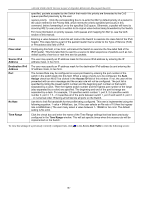
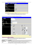
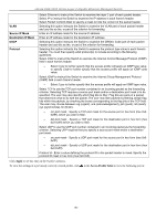
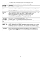
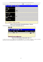
xStack DGS-3400 Series Layer 2 Gigabit Ethernet Managed Switch VLAN Source IP Mask Destination IP Mask DSCP Protocol Select Ethernet to instruct the Switch to examine the layer 2 part of each packet header. Select IP to instruct the Switch to examine the IP address in each frame's header. Select Packet Content Mask to specify a mask to hide the content of the packet header. Selecting this option instructs the Switch to examine the VLAN part of each packet header and use this as the, or part of the criterion for forwarding. Enter an IP address mask for the source IP address. Enter an IP address mask for the destination IP address. Selecting this option instructs the Switch to examine the DiffServ Code part of each packet header and use this as the, or part of the criterion for forwarding. Selecting this option instructs the Switch to examine the protocol type value in each frame's header. You must then specify what protocol(s) to include according to the following guidelines: Select ICMP to instruct the Switch to examine the Internet Control Message Protocol (ICMP) field in each frame's header. • Select Type to further specify that the access profile will apply an ICMP type value, or specify Code to further specify that the access profile will apply an ICMP code value. Select IGMP to instruct the Switch to examine the Internet Group Management Protocol (IGMP) field in each frame's header. • Select Type to further specify that the access profile will apply an IGMP type value. Select TCP to use the TCP port number contained in an incoming packet as the forwarding criterion. Selecting TCP requires a source port mask and/or a destination port mask is to be specified. The user may also identify which flag bits to filter. Flag bits are parts of a packet that determine what to do with the packet. The user may filter packets by filtering certain flag bits within the packets, by checking the boxes corresponding to the flag bits of the TCP field. The user may choose between urg (urgent), ack (acknowledgement), psh (push), rst (reset), syn (synchronize), fin (finish). • src port mask - Specify a TCP port mask for the source port in hex form (hex 0x00xffff), which you wish to filter. • dst port mask - Specify a TCP port mask for the destination port in hex form (hex 0x0-0xffff) which you wish to filter. Select UDP to use the UDP port number contained in an incoming packet as the forwarding criterion. Selecting UDP requires that you specify a source port mask and/or a destination port mask. • src port mask - Specify a UDP port mask for the source port in hex form (hex 0x00xffff). • dst port mask - Specify a UDP port mask for the destination port in hex form (hex 0x0-0xffff). Protocol id - Enter a value defining the protocol ID in the packet header to mask. Specify the protocol ID mask in hex form (hex 0x0-0xff). Click Apply to set this entry in the Switch's memory. To view the settings of a previously correctly created profile, click in the Access Profile Table to view the following screen: 192
-
 1
1 -
2
-
3
-
4
-
5
-
6
-
7
-
8
-
9
-
10
-
11
-
12
-
13
-
14
-
15
-
16
-
17
-
18
-
19
-
20
-
21
-
22
-
23
-
24
-
25
-
26
-
27
-
28
-
29
-
30
-
31
-
32
-
33
-
34
-
35
-
36
-
37
-
38
-
39
-
40
-
41
-
42
-
43
-
44
-
45
-
46
-
47
-
48
-
49
-
50
-
51
-
52
-
53
-
54
-
55
-
56
-
57
-
58
-
59
-
60
-
61
-
62
-
63
-
64
-
65
-
66
-
67
-
68
-
69
-
70
-
71
-
72
-
73
-
74
-
75
-
76
-
77
-
78
-
79
-
80
-
81
-
82
-
83
-
84
-
85
-
86
-
87
-
88
-
89
-
90
-
91
-
92
-
93
-
94
-
95
-
96
-
97
-
98
-
99
-
100
-
101
-
102
-
103
-
104
-
105
-
106
-
107
-
108
-
109
-
110
-
111
-
112
-
113
-
114
-
115
-
116
-
117
-
118
-
119
-
120
-
121
-
122
-
123
-
124
-
125
-
126
-
127
-
128
-
129
-
130
-
131
-
132
-
133
-
134
-
135
-
136
-
137
-
138
-
139
-
140
-
141
-
142
-
143
-
144
-
145
-
146
-
147
-
148
-
149
-
150
-
151
-
152
-
153
-
154
-
155
-
156
-
157
-
158
-
159
-
160
-
161
-
162
-
163
-
164
-
165
-
166
-
167
-
168
-
169
-
170
-
171
-
172
-
173
-
174
-
175
-
176
-
177
-
178
-
179
-
180
-
181
-
182
-
183
-
184
-
185
-
186
-
187
-
188
-
189
-
190
-
191
-
192
-
193
-
194
-
195
-
196
-
197
-
198
-
199
-
200
-
 201
201 -
 202
202 -
 203
203 -
 204
204 -
 205
205 -
 206
206 -
 207
207 -
 208
208 -
 209
209 -
 210
210 -
 211
211 -
212
-
213
-
214
-
215
-
216
-
217
-
218
-
219
-
220
-
221
-
222
-
223
-
224
-
225
-
226
-
227
-
228
-
229
-
230
-
231
-
232
-
233
-
234
-
235
-
236
-
237
-
238
-
239
-
240
-
241
-
242
-
243
-
244
-
245
-
246
-
247
-
248
-
249
-
250
-
251
-
252
-
253
-
254
-
255
-
256
-
257
-
258
-
259
-
260
-
261
-
262
-
263
-
264
-
265
-
266
-
267
-
268
-
269
-
270
-
271
-
272
-
273
-
274
-
275
-
276
-
277
-
278
-
279
-
280
-
281
-
282
-
283
-
284
-
285
-
286
-
287
-
288
-
289
-
290
-
291
-
292
-
293
-
294
-
295
-
296
-
297
-
298
-
299
-
300
-
301
-
302
-
303
-
304
-
305
-
306
-
307
-
308
-
309
-
310
-
311
-
312
-
313
-
314
-
315
-
316
-
317
-
318
-
319
-
320
-
321
-
322
-
323
-
324
-
325
-
326
-
327
-
328
-
329
-
330
-
331
-
332
-
333
-
334
-
335
-
336
-
337
-
338
-
339
-
340
-
341
-
342
-
343
-
344
-
345
-
346
-
347
-
348
-
349
-
350
-
351
-
352
-
353
-
354
-
355
-
356
 |
 |
