D-Link DGS-3426 User Manual - Page 174
STP Port Settings, STP Port Settings window
 |
View all D-Link DGS-3426 manuals
Add to My Manuals
Save this manual to your list of manuals |
Page 174 highlights
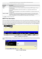
xStack DGS-3400 Series Layer 2 Gigabit Ethernet Managed Switch STP Port Settings STP can be set up on a port per port basis. To view the STP Port Settings window click Layer 2 Features > Spanning Tree > STP Port Settings: In addition to setting Spanning Tree parameters for use on the switch level, the Switch allows for the configuration of groups of ports, each port-group of which will have its own spanning tree, and will require some of its own configuration settings. An STP Group will use the switch-level parameters entered above, with the addition of Port Priority and Port Cost. An STP Group spanning tree works in the same way as the switch-level spanning tree, but the root bridge concept is replaced with a root port concept. A root port is a port of the group that is elected based on port priority and port cost, to be the connection to the network for the group. Redundant links will be blocked, just as redundant links are blocked on the switch level. The STP on the switch level blocks redundant links between switches (and similar network devices). The port level STP will block redundant links within an STP Group. Figure 7- 47. STP Port Settings window It is advisable to define an STP Group to correspond to a VLAN group of ports. The following STP Port Settings fields can be set: Parameter Description Unit Select the switch in the switch stack to be modified. From/To A consecutive group of ports may be configured starting with the selected port. External Cost This defines a metric that indicates the relative cost of forwarding packets to the specified port list. Port cost can be set automatically or as a metric value. The default value is 0 (auto). 0 (auto) - Setting 0 for the external cost will automatically set the speed for forwarding packets to the specified port(s) in the list for optimal efficiency. Default port cost: 100Mbps port = 200000. Gigabit port = 20000. value 1-200000000 - Define a value between 1 and 200000000 to determine the external cost. The lower the number, the greater the probability the port will be chosen to forward packets. Hello Time The time interval between transmissions of configuration messages by the designated port, to other devices on the bridged LAN. The user may choose a time between 1 and 10 seconds. The default is 2 seconds. This field is only operable when the Switch is enabled for MSTP. Migration When operating in RSTP mode, selecting yes forces the port that has been selected to transmit RSTP BPDUs. Edge Choosing the True parameter designates the port as an edge port. Edge ports cannot create loops, however an edge port can lose edge port status if a topology change creates a potential for a loop. An edge port normally should not receive BPDU packets. If a BPDU packet is received, it automatically loses edge port status. Choosing the False parameter indicates that the port does not have edge port status. P2P Choosing the True parameter indicates a point-to-point (P2P) shared link. P2P ports are similar to edge ports, however they are restricted in that a P2P port must operate in full 160
-
 1
1 -
2
-
3
-
4
-
5
-
6
-
7
-
8
-
9
-
10
-
11
-
12
-
13
-
14
-
15
-
16
-
17
-
18
-
19
-
20
-
21
-
22
-
23
-
24
-
25
-
26
-
27
-
28
-
29
-
30
-
31
-
32
-
33
-
34
-
35
-
36
-
37
-
38
-
39
-
40
-
41
-
42
-
43
-
44
-
45
-
46
-
47
-
48
-
49
-
50
-
51
-
52
-
53
-
54
-
55
-
56
-
57
-
58
-
59
-
60
-
61
-
62
-
63
-
64
-
65
-
66
-
67
-
68
-
69
-
70
-
71
-
72
-
73
-
74
-
75
-
76
-
77
-
78
-
79
-
80
-
81
-
82
-
83
-
84
-
85
-
86
-
87
-
88
-
89
-
90
-
91
-
92
-
93
-
94
-
95
-
96
-
97
-
98
-
99
-
100
-
101
-
102
-
103
-
104
-
105
-
106
-
107
-
108
-
109
-
110
-
111
-
112
-
113
-
114
-
115
-
116
-
117
-
118
-
119
-
120
-
121
-
122
-
123
-
124
-
125
-
126
-
127
-
128
-
129
-
130
-
131
-
132
-
133
-
134
-
135
-
136
-
137
-
138
-
139
-
140
-
141
-
142
-
143
-
144
-
145
-
146
-
147
-
148
-
149
-
150
-
151
-
152
-
153
-
154
-
155
-
156
-
157
-
158
-
159
-
160
-
161
-
162
-
163
-
164
-
165
-
166
-
167
-
168
-
 169
169 -
 170
170 -
 171
171 -
 172
172 -
 173
173 -
 174
174 -
 175
175 -
 176
176 -
 177
177 -
 178
178 -
 179
179 -
180
-
181
-
182
-
183
-
184
-
185
-
186
-
187
-
188
-
189
-
190
-
191
-
192
-
193
-
194
-
195
-
196
-
197
-
198
-
199
-
200
-
201
-
202
-
203
-
204
-
205
-
206
-
207
-
208
-
209
-
210
-
211
-
212
-
213
-
214
-
215
-
216
-
217
-
218
-
219
-
220
-
221
-
222
-
223
-
224
-
225
-
226
-
227
-
228
-
229
-
230
-
231
-
232
-
233
-
234
-
235
-
236
-
237
-
238
-
239
-
240
-
241
-
242
-
243
-
244
-
245
-
246
-
247
-
248
-
249
-
250
-
251
-
252
-
253
-
254
-
255
-
256
-
257
-
258
-
259
-
260
-
261
-
262
-
263
-
264
-
265
-
266
-
267
-
268
-
269
-
270
-
271
-
272
-
273
-
274
-
275
-
276
-
277
-
278
-
279
-
280
-
281
-
282
-
283
-
284
-
285
-
286
-
287
-
288
-
289
-
290
-
291
-
292
-
293
-
294
-
295
-
296
-
297
-
298
-
299
-
300
-
301
-
302
-
303
-
304
-
305
-
306
-
307
-
308
-
309
-
310
-
311
-
312
-
313
-
314
-
315
-
316
-
317
-
318
-
319
-
320
-
321
-
322
-
323
-
324
-
325
-
326
-
327
-
328
-
329
-
330
-
331
-
332
-
333
-
334
-
335
-
336
-
337
-
338
-
339
-
340
-
341
-
342
-
343
-
344
-
345
-
346
-
347
-
348
-
349
-
350
-
351
-
352
-
353
-
354
-
355
-
356
 |
 |
