D-Link DGS-3426 User Manual - Page 60
Stacking, Switches stacked in a Duplex Ring
 |
View all D-Link DGS-3426 manuals
Add to My Manuals
Save this manual to your list of manuals |
Page 60 highlights
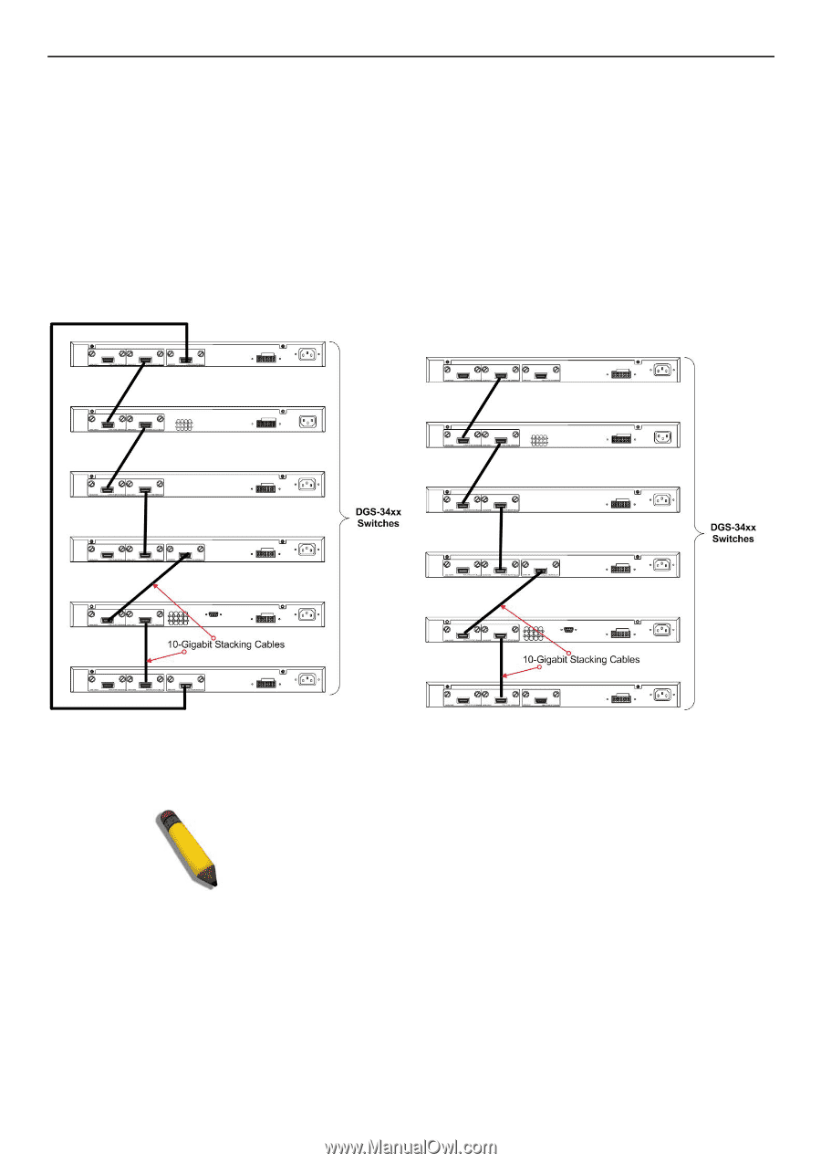
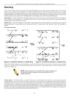
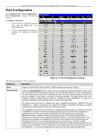
xStack DGS-3400 Series Layer 2 Gigabit Ethernet Managed Switch Stacking From firmware release v2.00 of this Switch, the xStack DGS-3400 series now supports switch stacking, where a set of twelve switches can be combined to be managed by one IP address through Telnet, the GUI interface (web), the console port or through SNMP. Each switch of this series has either two or three stacking slots located at the rear of the device, which can be used to add 10-gigabit DEM-410CX or DEM-410X stacking modules, sold separately. After adding these stacking ports, the user may connect these ports together using copper or fiber stacking cables (also sold separately) in one of two possible topologies. Duplex Ring - As shown in Figure 6-9, the Duplex Ring stacks switches in a ring or circle format where data can be transferred in two directions. This topology is very resilient because if there is a break in the ring, data can still be transferred through the stacking cables between switches in the stack. Duplex Chain - As shown in Figure 6-10, The Duplex Chain topology stacks switches together in a chain-link format. Using this method, data transfer is only possible in one direction and if there is a break in the chain, then data transfer will obviously be affected. Figure 6- 9. Switches stacked in a Duplex Ring Figure 6- 10. Switches stacked in a Duplex Chain Within each of these topologies, each switch plays a role in the Switch stack. These roles can be set by the user per individual Switch, or if desired, can be automatically determined by the switch stack. Three possible roles exist when stacking with the xStack DGS-3400 series. NOTE: Only ports 26 and 27 of the DGS-3427 support stacking. Port 25 cannot be used for stacking, and is to be used only as a 10Gigabit uplink port. Primary Master - The Primary Master is the leader of the stack. It will maintain normal operations, monitor operations and the running topology of the Stack. This switch will also assign Stack Unit IDs, synchronize configurations and transmit commands to remaining switches in the switch stack. The Primary Master can be manually set by assigning this Switch the highest priority (a lower number denotes a higher priority) before physically assembling the stack, or it can be determined automatically by the stack through an election process, which determines the lowest MAC address. It will then assign that switch as the Primary Master, if all priorities are the same. The Primary master is physically displayed by the seven segment LED to the far right on the front panel of the switch where this LED will flash between its given Box ID and 'H'. 46
-
 1
1 -
2
-
3
-
4
-
5
-
6
-
7
-
8
-
9
-
10
-
11
-
12
-
13
-
14
-
15
-
16
-
17
-
18
-
19
-
20
-
21
-
22
-
23
-
24
-
25
-
26
-
27
-
28
-
29
-
30
-
31
-
32
-
33
-
34
-
35
-
36
-
37
-
38
-
39
-
40
-
41
-
42
-
43
-
44
-
45
-
46
-
47
-
48
-
49
-
50
-
51
-
52
-
53
-
54
-
 55
55 -
 56
56 -
 57
57 -
 58
58 -
 59
59 -
 60
60 -
 61
61 -
 62
62 -
 63
63 -
 64
64 -
 65
65 -
66
-
67
-
68
-
69
-
70
-
71
-
72
-
73
-
74
-
75
-
76
-
77
-
78
-
79
-
80
-
81
-
82
-
83
-
84
-
85
-
86
-
87
-
88
-
89
-
90
-
91
-
92
-
93
-
94
-
95
-
96
-
97
-
98
-
99
-
100
-
101
-
102
-
103
-
104
-
105
-
106
-
107
-
108
-
109
-
110
-
111
-
112
-
113
-
114
-
115
-
116
-
117
-
118
-
119
-
120
-
121
-
122
-
123
-
124
-
125
-
126
-
127
-
128
-
129
-
130
-
131
-
132
-
133
-
134
-
135
-
136
-
137
-
138
-
139
-
140
-
141
-
142
-
143
-
144
-
145
-
146
-
147
-
148
-
149
-
150
-
151
-
152
-
153
-
154
-
155
-
156
-
157
-
158
-
159
-
160
-
161
-
162
-
163
-
164
-
165
-
166
-
167
-
168
-
169
-
170
-
171
-
172
-
173
-
174
-
175
-
176
-
177
-
178
-
179
-
180
-
181
-
182
-
183
-
184
-
185
-
186
-
187
-
188
-
189
-
190
-
191
-
192
-
193
-
194
-
195
-
196
-
197
-
198
-
199
-
200
-
201
-
202
-
203
-
204
-
205
-
206
-
207
-
208
-
209
-
210
-
211
-
212
-
213
-
214
-
215
-
216
-
217
-
218
-
219
-
220
-
221
-
222
-
223
-
224
-
225
-
226
-
227
-
228
-
229
-
230
-
231
-
232
-
233
-
234
-
235
-
236
-
237
-
238
-
239
-
240
-
241
-
242
-
243
-
244
-
245
-
246
-
247
-
248
-
249
-
250
-
251
-
252
-
253
-
254
-
255
-
256
-
257
-
258
-
259
-
260
-
261
-
262
-
263
-
264
-
265
-
266
-
267
-
268
-
269
-
270
-
271
-
272
-
273
-
274
-
275
-
276
-
277
-
278
-
279
-
280
-
281
-
282
-
283
-
284
-
285
-
286
-
287
-
288
-
289
-
290
-
291
-
292
-
293
-
294
-
295
-
296
-
297
-
298
-
299
-
300
-
301
-
302
-
303
-
304
-
305
-
306
-
307
-
308
-
309
-
310
-
311
-
312
-
313
-
314
-
315
-
316
-
317
-
318
-
319
-
320
-
321
-
322
-
323
-
324
-
325
-
326
-
327
-
328
-
329
-
330
-
331
-
332
-
333
-
334
-
335
-
336
-
337
-
338
-
339
-
340
-
341
-
342
-
343
-
344
-
345
-
346
-
347
-
348
-
349
-
350
-
351
-
352
-
353
-
354
-
355
-
356
 |
 |