D-Link DGS-3426 User Manual - Page 38
IP Address Assignment, show switch command
 |
View all D-Link DGS-3426 manuals
Add to My Manuals
Save this manual to your list of manuals |
Page 38 highlights
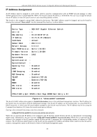
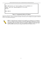
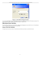
xStack DGS-3400 Series Layer 2 Gigabit Ethernet Managed Switch IP Address Assignment An IP Address must be assigned to each switch, which is used for communication with an SNMP network manager or other TCP/IP application (for example BOOTP, TFTP). The Switch's default IP address is 10.90.90.90. The user may change the default Switch IP address to meet the specification of your networking address scheme. The Switch is also assigned a unique MAC address by the factory. This MAC address cannot be changed, and can be found by entering the command "show switch" into the command line interface, as shown below. Device Type : DGS-3427 Gigabit Ethernet Switch Unit ID : 1 MAC Address : 00-19-5B-EF-6F-21 IP Address : 10.73.21.35 (Manual) VLAN Name : default Subnet Mask : 255.0.0.0 Default Gateway : 0.0.0.0 Boot PROM Version : Build 1.00-B13 Firmware Version : Build 2.35-B09 Hardware Version : 2A1G System Name : System Location : System Contact : Spanning Tree : Disabled GVRP : Disabled IGMP Snooping : Disabled MLD Snooping : Disabled TELNET : Enabled (TCP 23) WEB : Enabled (TCP 80) RMON : Disabled SSL status : Disabled SSH status : Disabled CTRL+C ESC q Quit SPACE n Next Page ENTER Next Entry a All Figure 4- 4. "show switch" command The Switch's MAC address also appears in Switch Information menu of the web-based management interface. The IP address for the Switch must be set before using the Web-based manager. The Switch IP address can be automatically set using BOOTP or DHCP protocols, in which case the actual address assigned to the Switch must be known. The IP address may be set using the Command Line Interface (CLI) over the console serial port as follows: Starting at the command line prompt, enter the command: config ipif System ipaddress xxx.xxx.xxx.xxx/yyy.yyy.yyy.yyy Where the x's represent the IP address to be assigned to the IP interface named System and the y's represent the corresponding subnet mask. Alternatively, the user can enter config ipif System ipaddress xxx.xxx.xxx.xxx/z. Where the x's represent the IP address to be assigned to the IP interface named System and the z represents the corresponding number of subnets in CIDR notation. The IP interface named System on the Switch can be assigned an IP address and subnet mask, which can then be used to connect a management station to the Switch's Telnet or Web-based management agent. 24
-
 1
1 -
2
-
3
-
4
-
5
-
6
-
7
-
8
-
9
-
10
-
11
-
12
-
13
-
14
-
15
-
16
-
17
-
18
-
19
-
20
-
21
-
22
-
23
-
24
-
25
-
26
-
27
-
28
-
29
-
30
-
31
-
32
-
 33
33 -
 34
34 -
 35
35 -
 36
36 -
 37
37 -
 38
38 -
 39
39 -
 40
40 -
 41
41 -
 42
42 -
 43
43 -
44
-
45
-
46
-
47
-
48
-
49
-
50
-
51
-
52
-
53
-
54
-
55
-
56
-
57
-
58
-
59
-
60
-
61
-
62
-
63
-
64
-
65
-
66
-
67
-
68
-
69
-
70
-
71
-
72
-
73
-
74
-
75
-
76
-
77
-
78
-
79
-
80
-
81
-
82
-
83
-
84
-
85
-
86
-
87
-
88
-
89
-
90
-
91
-
92
-
93
-
94
-
95
-
96
-
97
-
98
-
99
-
100
-
101
-
102
-
103
-
104
-
105
-
106
-
107
-
108
-
109
-
110
-
111
-
112
-
113
-
114
-
115
-
116
-
117
-
118
-
119
-
120
-
121
-
122
-
123
-
124
-
125
-
126
-
127
-
128
-
129
-
130
-
131
-
132
-
133
-
134
-
135
-
136
-
137
-
138
-
139
-
140
-
141
-
142
-
143
-
144
-
145
-
146
-
147
-
148
-
149
-
150
-
151
-
152
-
153
-
154
-
155
-
156
-
157
-
158
-
159
-
160
-
161
-
162
-
163
-
164
-
165
-
166
-
167
-
168
-
169
-
170
-
171
-
172
-
173
-
174
-
175
-
176
-
177
-
178
-
179
-
180
-
181
-
182
-
183
-
184
-
185
-
186
-
187
-
188
-
189
-
190
-
191
-
192
-
193
-
194
-
195
-
196
-
197
-
198
-
199
-
200
-
201
-
202
-
203
-
204
-
205
-
206
-
207
-
208
-
209
-
210
-
211
-
212
-
213
-
214
-
215
-
216
-
217
-
218
-
219
-
220
-
221
-
222
-
223
-
224
-
225
-
226
-
227
-
228
-
229
-
230
-
231
-
232
-
233
-
234
-
235
-
236
-
237
-
238
-
239
-
240
-
241
-
242
-
243
-
244
-
245
-
246
-
247
-
248
-
249
-
250
-
251
-
252
-
253
-
254
-
255
-
256
-
257
-
258
-
259
-
260
-
261
-
262
-
263
-
264
-
265
-
266
-
267
-
268
-
269
-
270
-
271
-
272
-
273
-
274
-
275
-
276
-
277
-
278
-
279
-
280
-
281
-
282
-
283
-
284
-
285
-
286
-
287
-
288
-
289
-
290
-
291
-
292
-
293
-
294
-
295
-
296
-
297
-
298
-
299
-
300
-
301
-
302
-
303
-
304
-
305
-
306
-
307
-
308
-
309
-
310
-
311
-
312
-
313
-
314
-
315
-
316
-
317
-
318
-
319
-
320
-
321
-
322
-
323
-
324
-
325
-
326
-
327
-
328
-
329
-
330
-
331
-
332
-
333
-
334
-
335
-
336
-
337
-
338
-
339
-
340
-
341
-
342
-
343
-
344
-
345
-
346
-
347
-
348
-
349
-
350
-
351
-
352
-
353
-
354
-
355
-
356
 |
 |
