D-Link DGS-3426 User Manual - Page 117
Single IP vs. Switch Stacking, SIM Using the Web Interface, SIM Settings window disabled
 |
View all D-Link DGS-3426 manuals
Add to My Manuals
Save this manual to your list of manuals |
Page 117 highlights
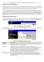
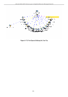
xStack DGS-3400 Series Layer 2 Gigabit Ethernet Managed Switch Single IP vs. Switch Stacking Single IP and Switch Stacking are two different entities and should not be equated by users. Within a switch stack, all functions are shared among switches in the stack and this switch stack is treated as one switch. Layer 2 and Layer 3 features, such as VLAN configurations and packet routing can be configured across switches in the stack. For example, mirroring functions can be shared within the stack, so a mirror target port may be on one switch in the stack and the source ports may be on another. For Single IP Management, switches are separate entities that share a common IP address. Therefore, Layer 2 and Layer 3 functions CANNOT be shared among switches in the Single IP group. The purpose of the Single IP Management function is to share firmware and configuration files among switches within the Single IP Group. To have similar configurations on switches within the Single IP Group, users can upload identical configuration files to the Single IP Group using the Configuration File Backup/Restore window located under the the Single IP heading on the switch, and described later in this section. Once this file is entered and uploaded to switches within the group, most configurations should be the same for the switches in the Single IP Group. SIM Using the Web Interface All xStack DGS-3400 Series Switches are set as Candidate (CaS) switches as their factory default configuration and Single IP Management will be disabled. To enable SIM for the Switch using the Web interface, go to the Single IP Management Settings folder and click the SIM Settings link, revealing the following window. Figure 6- 73. SIM Settings window (disabled) Change the SIM State to Enabled using the pull down menu and click Apply. The screen will then refresh and the SIM Settings window will look like this: Parameter SIM State Role State Discovery Interval Figure 6- 74. SIM Settings window (enabled) Description Use the pull-down menu to either enable or disable the SIM state on the Switch. Disabled will render all SIM functions on the Switch inoperable. Use the pull-down menu to change the SIM role of the Switch. The two choices are: Candidate - A Candidate Switch (CaS) is not the member of a SIM group but is connected to a Commander Switch. This is the default setting for the SIM role of the DGS-3400 Series. Commander - Choosing this parameter will make the Switch a Commander Switch (CS). The user may join other switches to this Switch, over Ethernet, to be part of its SIM group. Choosing this option will also enable the Switch to be configured for SIM. The user may set the discovery protocol interval, in seconds that the Switch will send out discovery packets. Returning information to a Commander Switch will include information about other switches connected to it. (Ex. MS, CaS). The user may set the Discovery Interval from 30 to 90 seconds. 103
-
 1
1 -
2
-
3
-
4
-
5
-
6
-
7
-
8
-
9
-
10
-
11
-
12
-
13
-
14
-
15
-
16
-
17
-
18
-
19
-
20
-
21
-
22
-
23
-
24
-
25
-
26
-
27
-
28
-
29
-
30
-
31
-
32
-
33
-
34
-
35
-
36
-
37
-
38
-
39
-
40
-
41
-
42
-
43
-
44
-
45
-
46
-
47
-
48
-
49
-
50
-
51
-
52
-
53
-
54
-
55
-
56
-
57
-
58
-
59
-
60
-
61
-
62
-
63
-
64
-
65
-
66
-
67
-
68
-
69
-
70
-
71
-
72
-
73
-
74
-
75
-
76
-
77
-
78
-
79
-
80
-
81
-
82
-
83
-
84
-
85
-
86
-
87
-
88
-
89
-
90
-
91
-
92
-
93
-
94
-
95
-
96
-
97
-
98
-
99
-
100
-
101
-
102
-
103
-
104
-
105
-
106
-
107
-
108
-
109
-
110
-
111
-
 112
112 -
 113
113 -
 114
114 -
 115
115 -
 116
116 -
 117
117 -
 118
118 -
 119
119 -
 120
120 -
 121
121 -
 122
122 -
123
-
124
-
125
-
126
-
127
-
128
-
129
-
130
-
131
-
132
-
133
-
134
-
135
-
136
-
137
-
138
-
139
-
140
-
141
-
142
-
143
-
144
-
145
-
146
-
147
-
148
-
149
-
150
-
151
-
152
-
153
-
154
-
155
-
156
-
157
-
158
-
159
-
160
-
161
-
162
-
163
-
164
-
165
-
166
-
167
-
168
-
169
-
170
-
171
-
172
-
173
-
174
-
175
-
176
-
177
-
178
-
179
-
180
-
181
-
182
-
183
-
184
-
185
-
186
-
187
-
188
-
189
-
190
-
191
-
192
-
193
-
194
-
195
-
196
-
197
-
198
-
199
-
200
-
201
-
202
-
203
-
204
-
205
-
206
-
207
-
208
-
209
-
210
-
211
-
212
-
213
-
214
-
215
-
216
-
217
-
218
-
219
-
220
-
221
-
222
-
223
-
224
-
225
-
226
-
227
-
228
-
229
-
230
-
231
-
232
-
233
-
234
-
235
-
236
-
237
-
238
-
239
-
240
-
241
-
242
-
243
-
244
-
245
-
246
-
247
-
248
-
249
-
250
-
251
-
252
-
253
-
254
-
255
-
256
-
257
-
258
-
259
-
260
-
261
-
262
-
263
-
264
-
265
-
266
-
267
-
268
-
269
-
270
-
271
-
272
-
273
-
274
-
275
-
276
-
277
-
278
-
279
-
280
-
281
-
282
-
283
-
284
-
285
-
286
-
287
-
288
-
289
-
290
-
291
-
292
-
293
-
294
-
295
-
296
-
297
-
298
-
299
-
300
-
301
-
302
-
303
-
304
-
305
-
306
-
307
-
308
-
309
-
310
-
311
-
312
-
313
-
314
-
315
-
316
-
317
-
318
-
319
-
320
-
321
-
322
-
323
-
324
-
325
-
326
-
327
-
328
-
329
-
330
-
331
-
332
-
333
-
334
-
335
-
336
-
337
-
338
-
339
-
340
-
341
-
342
-
343
-
344
-
345
-
346
-
347
-
348
-
349
-
350
-
351
-
352
-
353
-
354
-
355
-
356
 |
 |
