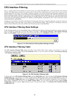
D-Link DGS-3426 User Manual - Page 201
Class, Flow Label, Source IPv6, Address, Destination IPv6, Assign, Access ID, Rx Rate, Time Range
 |
View all D-Link DGS-3426 manuals
Add to My Manuals
Save this manual to your list of manuals |
Page 201 highlights
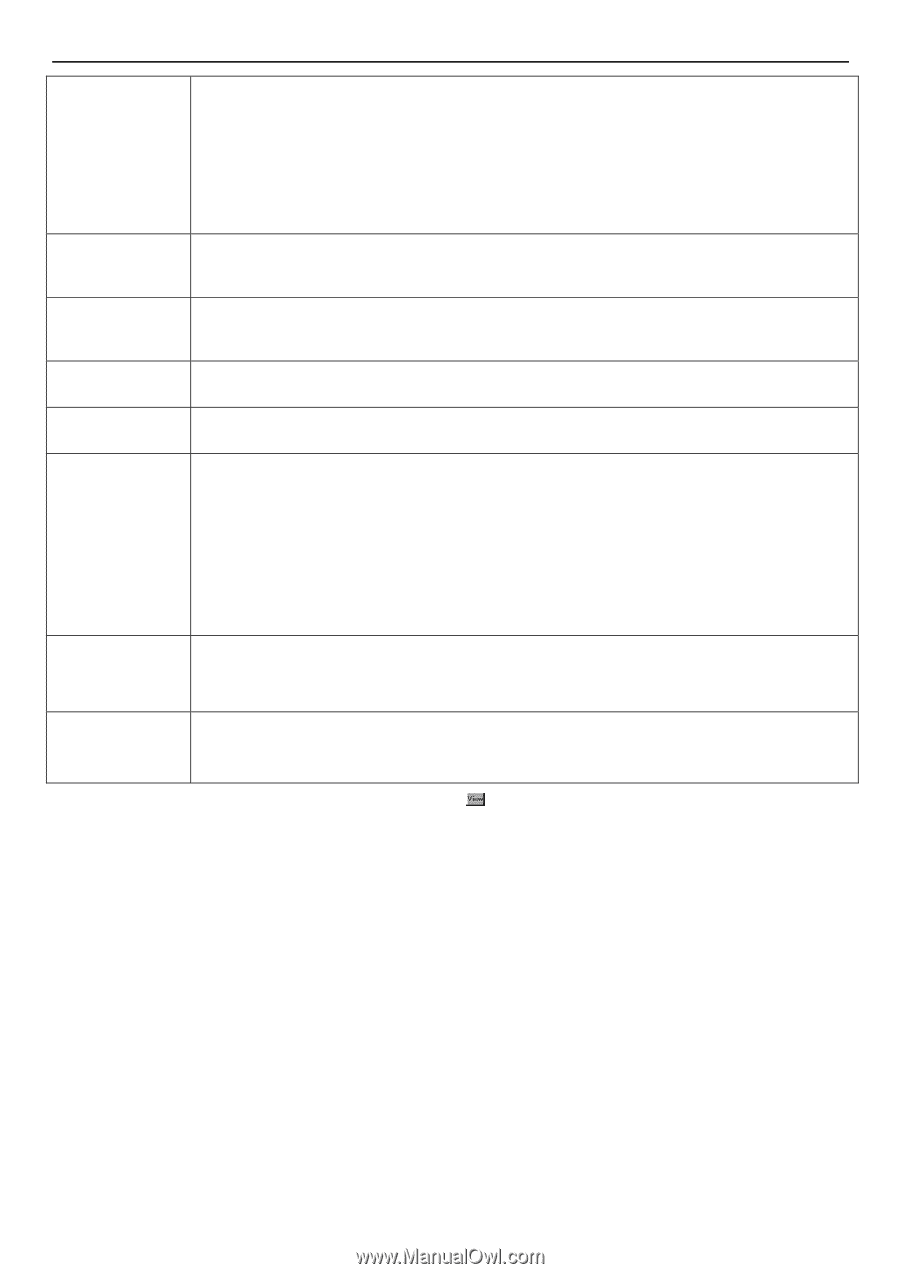
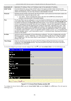
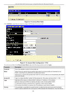
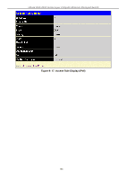
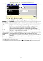
xStack DGS-3400 Series Layer 2 Gigabit Ethernet Managed Switch Class Flow Label Source IPv6 Address Destination IPv6 Address Port Rx Rate Time Range specified, packets accepted by the Switch that match this priority are forwarded to the CoS queue specified previously by the user. replace priority − Click the corresponding box to re-write the 802.1p default priority of a packet to the value entered in the Priority field, which meets the criteria specified previously in this command, before forwarding it on to the specified CoS queue. Otherwise, a packet will have its incoming 802.1p user priority re-written to its original value before being forwarded by the Switch. For more information on priority queues, CoS queues and mapping for 802.1p, see the QoS section of this manual. Entering a value between 0 and 255 will instruct the Switch to examine the class field of the IPv6 header. This class field is a part of the packet header that is similar to the Type of Service (ToS) or Precedence bits field of IPv4. Configuring this field, in hex form, will instruct the Switch to examine the flow label field of the IPv6 header. This flow label field is used by a source to label sequences of packets such as nondefault quality of service or real time service packets. The user may specify an IP address mask for the source IPv6 address by entering the IP address mask, in hex form. The user may specify an IP address mask for the destination IPv6 address by and entering the IP address mask, in hex form. The Access Rule may be configured on a per-port basis by entering the port number of the switch in the switch stack into this field. When a range of ports is to be configured, the Auto Assign check box MUST be clicked in the Access ID field of this window. If not, the user will be presented with an error message and the access rule will not be configured. The port list is specified by listing the lowest switch number and the beginning port number on that switch, separated by a colon. Then the highest switch number and the highest port number of the range (also separated by a colon) are specified. The beginning and end of the port list range are separated by a dash. For example, 1:3 specifies switch number 1, port 3. 2:4 specifies switch number 2, port 4. 1:3 - 2:4 specifies all of the ports between switch 1, port 3 and switch 2, port 4 − in numerical order. Entering all will denote all ports on the Switch. Use this to limit Rx bandwidth for the profile being configured. This rate is implemented using the following equation: 1 value = 64kbit/sec. (ex. If the user selects an Rx rate of 10 then the ingress rate is 640kbit/sec.) The user many select a value between 1- 156249 or No Limit. The default setting is No Limit. Click the check box and enter the name of the Time Range settings that has been previously configured in the Time Range window. This will set specific times when this access rule will be implemented on the Switch. To view the settings of a previously correctly configured rule, click in the Access Rule Table to view the following screen: 187
-
 1
1 -
2
-
3
-
4
-
5
-
6
-
7
-
8
-
9
-
10
-
11
-
12
-
13
-
14
-
15
-
16
-
17
-
18
-
19
-
20
-
21
-
22
-
23
-
24
-
25
-
26
-
27
-
28
-
29
-
30
-
31
-
32
-
33
-
34
-
35
-
36
-
37
-
38
-
39
-
40
-
41
-
42
-
43
-
44
-
45
-
46
-
47
-
48
-
49
-
50
-
51
-
52
-
53
-
54
-
55
-
56
-
57
-
58
-
59
-
60
-
61
-
62
-
63
-
64
-
65
-
66
-
67
-
68
-
69
-
70
-
71
-
72
-
73
-
74
-
75
-
76
-
77
-
78
-
79
-
80
-
81
-
82
-
83
-
84
-
85
-
86
-
87
-
88
-
89
-
90
-
91
-
92
-
93
-
94
-
95
-
96
-
97
-
98
-
99
-
100
-
101
-
102
-
103
-
104
-
105
-
106
-
107
-
108
-
109
-
110
-
111
-
112
-
113
-
114
-
115
-
116
-
117
-
118
-
119
-
120
-
121
-
122
-
123
-
124
-
125
-
126
-
127
-
128
-
129
-
130
-
131
-
132
-
133
-
134
-
135
-
136
-
137
-
138
-
139
-
140
-
141
-
142
-
143
-
144
-
145
-
146
-
147
-
148
-
149
-
150
-
151
-
152
-
153
-
154
-
155
-
156
-
157
-
158
-
159
-
160
-
161
-
162
-
163
-
164
-
165
-
166
-
167
-
168
-
169
-
170
-
171
-
172
-
173
-
174
-
175
-
176
-
177
-
178
-
179
-
180
-
181
-
182
-
183
-
184
-
185
-
186
-
187
-
188
-
189
-
190
-
191
-
192
-
193
-
194
-
195
-
 196
196 -
 197
197 -
 198
198 -
 199
199 -
 200
200 -
 201
201 -
 202
202 -
 203
203 -
 204
204 -
 205
205 -
 206
206 -
207
-
208
-
209
-
210
-
211
-
212
-
213
-
214
-
215
-
216
-
217
-
218
-
219
-
220
-
221
-
222
-
223
-
224
-
225
-
226
-
227
-
228
-
229
-
230
-
231
-
232
-
233
-
234
-
235
-
236
-
237
-
238
-
239
-
240
-
241
-
242
-
243
-
244
-
245
-
246
-
247
-
248
-
249
-
250
-
251
-
252
-
253
-
254
-
255
-
256
-
257
-
258
-
259
-
260
-
261
-
262
-
263
-
264
-
265
-
266
-
267
-
268
-
269
-
270
-
271
-
272
-
273
-
274
-
275
-
276
-
277
-
278
-
279
-
280
-
281
-
282
-
283
-
284
-
285
-
286
-
287
-
288
-
289
-
290
-
291
-
292
-
293
-
294
-
295
-
296
-
297
-
298
-
299
-
300
-
301
-
302
-
303
-
304
-
305
-
306
-
307
-
308
-
309
-
310
-
311
-
312
-
313
-
314
-
315
-
316
-
317
-
318
-
319
-
320
-
321
-
322
-
323
-
324
-
325
-
326
-
327
-
328
-
329
-
330
-
331
-
332
-
333
-
334
-
335
-
336
-
337
-
338
-
339
-
340
-
341
-
342
-
343
-
344
-
345
-
346
-
347
-
348
-
349
-
350
-
351
-
352
-
353
-
354
-
355
-
356
 |
 |