Dell OptiPlex GX300 User Guide - Page 18
Inserting the New Drive Into the Drive Bay
 |
View all Dell OptiPlex GX300 manuals
Add to My Manuals
Save this manual to your list of manuals |
Page 18 highlights
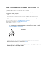
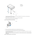
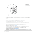
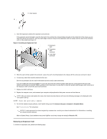
1 Metal tab 2 Drive bracket 3 Screws (4) To further ensure proper positioning of the drive in the chassis, insert and tighten all four screws in the order in which the holes are numbered (the holes are marked "1" through "4"). 7. Slide the new drive into the drive bay until the drive snaps securely into place (see Figure 3). Make sure that both bracket tabs snap into place in the drive bay. Figure 3. Inserting the New Drive Into the Drive Bay 1 Drive 8. Connect a DC power cable to the power input connector on the back of the drive (see Figure 4). 9. Connect the appropriate interface cable to the interface connector on the back of the drive (see Figure 4). If your system came with an EIDE CD-ROM or tape drive, use the spare connector on the existing interface cable. Otherwise, use the EIDE interface cable provided in the drive kit. NOTICE: You must match the colored strip on the cable with pin 1 on the drive's interface connector to avoid possible damage to your system. Figure 4. Attaching Diskette Drive or Tape Drive Cables
-
 1
1 -
2
-
3
-
4
-
5
-
6
-
7
-
8
-
9
-
10
-
11
-
12
-
 13
13 -
 14
14 -
 15
15 -
 16
16 -
 17
17 -
 18
18 -
 19
19 -
 20
20 -
 21
21 -
 22
22 -
 23
23 -
24
-
25
-
26
-
27
-
28
-
29
-
30
-
31
-
32
-
33
-
34
-
35
-
36
-
37
-
38
-
39
-
40
-
41
-
42
-
43
-
44
-
45
-
46
-
47
-
48
-
49
-
50
-
51
-
52
-
53
-
54
-
55
-
56
-
57
-
58
-
59
-
60
-
61
-
62
-
63
-
64
-
65
-
66
-
67
-
68
-
69
-
70
-
71
-
72
-
73
-
74
-
75
-
76
-
77
-
78
-
79
-
80
-
81
-
82
-
83
-
84
-
85
-
86
-
87
-
88
-
89
-
90
-
91
 |
 |
