Dell OptiPlex GX300 User Guide - Page 37
System Board Components - processor
 |
View all Dell OptiPlex GX300 manuals
Add to My Manuals
Save this manual to your list of manuals |
Page 37 highlights
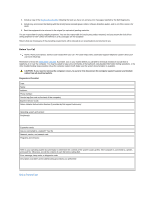
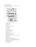
System Board Components Figure 3 shows the system board and the location of all its sockets and connectors. Figure 3. System Board Components 1 CD-ROM drive audio interface connector 2 Serial port 1 connector 3 Parallel port connector 4 Serial port 2 connector 5 Fan connector 6 Voltage regulator module (VRM) connector 7 Microphone connector 8 Line-out connector 9 Line-in connector 10 Keyboard and mouse connectors 11 Universal Serial Bus (USB) connectors 12 Secondary processor connector 13 Telephony connector 14 Network interface controller (NIC) connector 15 Primary processor connector 16 Accelerated graphics port (AGP) connector 17 Peripheral Component Interconnect (PCI) expansion card connectors (5) 18 3.3-volt (V) power connector 19 Power connector 20 Diskette-drive interface connector 21 Rambus in-line memory module (RIMM) sockets (2) 22 Suspend-to-random-access memory (RAM) light-emitting diode (LED) 23 Primary enhanced integrated drive electronics (EIDE) interface connector 24 Secondary EIDE interface connector 25 Control panel connector 26 External speaker connector
-
 1
1 -
2
-
3
-
4
-
5
-
6
-
7
-
8
-
9
-
10
-
11
-
12
-
13
-
14
-
15
-
16
-
17
-
18
-
19
-
20
-
21
-
22
-
23
-
24
-
25
-
26
-
27
-
28
-
29
-
30
-
31
-
 32
32 -
 33
33 -
 34
34 -
 35
35 -
 36
36 -
 37
37 -
 38
38 -
 39
39 -
 40
40 -
 41
41 -
 42
42 -
43
-
44
-
45
-
46
-
47
-
48
-
49
-
50
-
51
-
52
-
53
-
54
-
55
-
56
-
57
-
58
-
59
-
60
-
61
-
62
-
63
-
64
-
65
-
66
-
67
-
68
-
69
-
70
-
71
-
72
-
73
-
74
-
75
-
76
-
77
-
78
-
79
-
80
-
81
-
82
-
83
-
84
-
85
-
86
-
87
-
88
-
89
-
90
-
91
 |
 |
