Dell OptiPlex GX300 User Guide - Page 27
Disk Drives: Dell™ OptiPlex™ GX300 System User's Guide
 |
View all Dell OptiPlex GX300 manuals
Add to My Manuals
Save this manual to your list of manuals |
Page 27 highlights
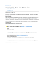
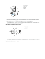
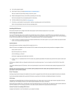
Back to Contents Page Hard-Disk Drives: Dell™ OptiPlex™ GX300 System User's Guide Installing an EIDE Hard-Disk Drive Installing SCSI Devices Installing an EIDE Hard-Disk Drive Up to two enhanced integrated drive electronics (EIDE) drives (one of which must be 1 inch high or less) can be installed in the hard-disk drive bracket below the drive cage. The first EIDE drive is installed in the 1-inch (lower) drive bay labeled "HD1"; a second drive is installed in the 1.6inch bay labeled "HD2." EIDE Drive Addressing All EIDE devices should be configured for the Cable Select jumper position, which assigns master and slave status to devices by their position on the interface cable. When two EIDE devices are connected to a single EIDE interface cable and are configured for the Cable Select jumper position, the device attached to the last connector on the interface cable is the master or boot device (drive 0), and the device attached to the middle connector on the interface cable is the slave device (drive 1). Refer to the drive documentation in your upgrade kit for information on setting devices to the Cable Select jumper position. With the two EIDE interface connectors on the system board, your system can support up to four EIDE devices. EIDE hard-disk drives should be connected to the EIDE interface connector labeled "IDE1." EIDE tape drives and CD-ROM drives should be connected to the EIDE interface connector labeled "IDE2." Installing an EIDE Hard-Disk Drive in the Hard-Disk Drive Bracket To install an EIDE hard-disk drive in the hard-disk drive bracket, perform the following steps. CAUTION: Before you remove the computer cover, see "Safety First - For You and Your Computer." 1. If you are replacing a hard-disk drive that contains data you want to keep, be sure to make a backup of your files before you begin this procedure. 2. Prepare the drive for installation. NOTICE: Ground yourself by touching an unpainted metal surface on the back of the computer. NOTICE: When you unpack the drive, do not set it on a hard surface, which may damage the drive. Instead, set the drive on a surface such as a foam pad that will sufficiently cushion it. Check the documentation for the drive to verify that it is configured for your computer system. 3. Remove the computer cover as instructed in "Removing and Replacing the Computer Cover." 4. Remove the drive bracket from the chassis. If a hard-disk drive is already installed in the drive bracket, disconnect the DC power cable and EIDE cable from the drive. Remove the screw securing the hard-disk drive bracket to the drive cage in the chassis. Grasp the bracket, and rotate it outward from the chassis until the sliding tab clears the slide rail on the drive cage (see Figure 1). Lift the bracket up slightly to free its hinge tabs from the chassis slots. Figure 1. Removing the Hard-Disk Drive Bracket
-
 1
1 -
2
-
3
-
4
-
5
-
6
-
7
-
8
-
9
-
10
-
11
-
12
-
13
-
14
-
15
-
16
-
17
-
18
-
19
-
20
-
21
-
 22
22 -
 23
23 -
 24
24 -
 25
25 -
 26
26 -
 27
27 -
 28
28 -
 29
29 -
 30
30 -
 31
31 -
 32
32 -
33
-
34
-
35
-
36
-
37
-
38
-
39
-
40
-
41
-
42
-
43
-
44
-
45
-
46
-
47
-
48
-
49
-
50
-
51
-
52
-
53
-
54
-
55
-
56
-
57
-
58
-
59
-
60
-
61
-
62
-
63
-
64
-
65
-
66
-
67
-
68
-
69
-
70
-
71
-
72
-
73
-
74
-
75
-
76
-
77
-
78
-
79
-
80
-
81
-
82
-
83
-
84
-
85
-
86
-
87
-
88
-
89
-
90
-
91
 |
 |