Dell OptiPlex GX300 User Guide - Page 38
System Board Jumpers, System Board Labels
 |
View all Dell OptiPlex GX300 manuals
Add to My Manuals
Save this manual to your list of manuals |
Page 38 highlights
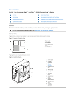
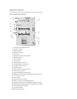
27 Remote Wakeup power connector 28 Standby LED 29 Password jumper 30 Auxiliary hard-disk drive access indicator connector 31 RTCRST jumper 32 Battery socket System Board Jumpers Figure 4 shows the location of the jumpers on the system board. Table 1 lists the system board jumpers and their settings. Figure 4. System Board Jumpers Jumpers are small blocks on a circuit board with two or more pins emerging from them. Plastic plugs containing a wire fit down over the pins. The wire connects the pins and creates a circuit. NOTICE: Make sure your system is turned off before you change a jumper setting. Otherwise, damage to your system or unpredictable results may occur. To change a jumper setting, pull the plug off its pin(s) and carefully fit it down onto the pin(s) indicated. Table 1. System-Board Jumper Settings Jumper PSWD Setting (default) Description Password features are enabled. RTCRST jumpered Password features are disabled. Real-time clock reset. Can be used for troubleshooting purposes. unjumpered System Board Labels Table 2 lists the labels for connectors and sockets on your system board, and it gives a brief description of their functions. Table 2. System Board Connectors and Sockets Connector or Socket AUX_LED BATT CD_IN RIMM_x DSKT ENET EXT_SPKR Description Hard-disk drive LED connector Battery socket CD-ROM audio interface connector RIMM socket Diskette/tape drive interface connector Integrated NIC connector External speaker connector
-
 1
1 -
2
-
3
-
4
-
5
-
6
-
7
-
8
-
9
-
10
-
11
-
12
-
13
-
14
-
15
-
16
-
17
-
18
-
19
-
20
-
21
-
22
-
23
-
24
-
25
-
26
-
27
-
28
-
29
-
30
-
31
-
32
-
 33
33 -
 34
34 -
 35
35 -
 36
36 -
 37
37 -
 38
38 -
 39
39 -
 40
40 -
 41
41 -
 42
42 -
 43
43 -
44
-
45
-
46
-
47
-
48
-
49
-
50
-
51
-
52
-
53
-
54
-
55
-
56
-
57
-
58
-
59
-
60
-
61
-
62
-
63
-
64
-
65
-
66
-
67
-
68
-
69
-
70
-
71
-
72
-
73
-
74
-
75
-
76
-
77
-
78
-
79
-
80
-
81
-
82
-
83
-
84
-
85
-
86
-
87
-
88
-
89
-
90
-
91
 |
 |
