Dell OptiPlex GX300 User Guide - Page 63
Upgrading an Existing Microprocessor
 |
View all Dell OptiPlex GX300 manuals
Add to My Manuals
Save this manual to your list of manuals |
Page 63 highlights
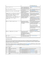
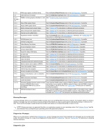
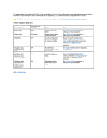
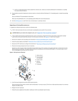
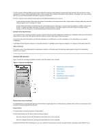
NOTE: If a setup password has been assigned by someone else, contact your network administrator for information on resetting the chassis intrusion detector. 12. If you installed a second microprocessor and your system is running the Microsoft Windows NT 4.0 operating system, reinstall the operating system. See your Windows NT documentation for instructions. When you reinstall Windows NT 4.0, the operating system detects the second microprocessor. 13. Run the Dell Diagnostics to verify that the new microprocessor is operating correctly. Upgrading an Existing Microprocessor To upgrade an existing microprocessor, perform the following steps. NOTE: Dell recommends that only a technically knowledgeable person perform this procedure. CAUTION: Before you remove the computer cover, see "Safety First- For You and Your Computer." NOTE: Before disconnecting a peripheral from the system or removing a component from the system board, verify that the standby power LED on the system board has turned off. For the location of this LED, see Figure 3 in "Inside Your Computer." 1. Remove the computer cover according to the instructions in "Removing and Replacing the Computer Cover." 2. Rotate the power supply as described in "Rotating the Power Supply Away From the System Board." 3. Remove the AGP card brace according to the instructions in "Removing and Replacing the AGP Card Brace." 4. Remove the existing microprocessor from its connector. Squeeze in on the two pairs of tabs on the airflow shroud and lift it away. Press outward on the guide bracket tabs to release them from the processor/heat sink assembly. Then pull the processor/heat sink assembly out of its connector (see Figure 1). You must use up to 15 lb of force to disengage the processor from the connector. Figure 1. Microprocessor Removal 1 Airflow shroud 2 Processor/heat sink assembly 3 Guide bracket 4 Second processor 5 Cooling fan 5. Insert the new microprocessor into the system board connector. Press the processor firmly into its connector until it is fully seated. You must use up to 25 lb of force to fully seat the processor in its connector. Replace the airflow shroud. 6. Replace the AGP card brace. 7. Rotate the power supply back into position, making sure that the securing tab snaps into place.
-
 1
1 -
2
-
3
-
4
-
5
-
6
-
7
-
8
-
9
-
10
-
11
-
12
-
13
-
14
-
15
-
16
-
17
-
18
-
19
-
20
-
21
-
22
-
23
-
24
-
25
-
26
-
27
-
28
-
29
-
30
-
31
-
32
-
33
-
34
-
35
-
36
-
37
-
38
-
39
-
40
-
41
-
42
-
43
-
44
-
45
-
46
-
47
-
48
-
49
-
50
-
51
-
52
-
53
-
54
-
55
-
56
-
57
-
 58
58 -
 59
59 -
 60
60 -
 61
61 -
 62
62 -
 63
63 -
 64
64 -
 65
65 -
 66
66 -
 67
67 -
 68
68 -
69
-
70
-
71
-
72
-
73
-
74
-
75
-
76
-
77
-
78
-
79
-
80
-
81
-
82
-
83
-
84
-
85
-
86
-
87
-
88
-
89
-
90
-
91
 |
 |