Dell OptiPlex GX300 User Guide - Page 39
Removing and Replacing the AGP Card Brace - ram
 |
View all Dell OptiPlex GX300 manuals
Add to My Manuals
Save this manual to your list of manuals |
Page 39 highlights
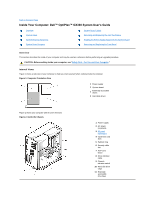
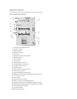
FAN IDEn INTRUSION KYBD MONITOR MOUSE PANEL PAR PCIn* POWER_1 POWER_2 PROC_0 PROC_1 SER STANDBY STR USB TAPI WUOL Microprocessor fan connector EIDE interface connector Chassis intrusion switch connector Keyboard connector Video connector Mouse connector Control panel connector Parallel port connector; sometimes referred to as LPT1 PCI expansion-card connector Main power input connector 3.3-V power input connector Primary microprocessor connector Secondary microprocessor connector Serial port connectors Standby power LED Suspend-to-RAM LED USB connectors Telephony connector Remote Wakeup power connector Removing and Replacing the AGP Card Brace To access any expansion cards or components on the system board, you must first remove the AGP card brace that secures an AGP card in the AGP socket. CAUTION: Before you remove the computer cover, see "Safety First-For You and Your Computer." 1. Remove the computer cover. 2. Remove the screw securing the AGP card brace to the chassis (see Figure 5). Figure 5. Removing the AGP Card Brace 1 Card guide 2 AGP card brace 3 Screw 4 Plastic AGP card guide 5 Tab 6 Slot 3. Rotate the brace up until it disengages from the card guide at the front of the chassis. Then lift it away from the chassis. To replace the brace, perform the following steps: 1. Insert the tabs on one end of the brace into the slots on the card guide at the front of the chassis (see Figure 5). 2. Lower the brace, ensuring that the plastic AGP card guide on the bottom of the brace is engaged with the top of the AGP card. 3. Replace the screw that secures the brace to the chassis.
-
 1
1 -
2
-
3
-
4
-
5
-
6
-
7
-
8
-
9
-
10
-
11
-
12
-
13
-
14
-
15
-
16
-
17
-
18
-
19
-
20
-
21
-
22
-
23
-
24
-
25
-
26
-
27
-
28
-
29
-
30
-
31
-
32
-
33
-
 34
34 -
 35
35 -
 36
36 -
 37
37 -
 38
38 -
 39
39 -
 40
40 -
 41
41 -
 42
42 -
 43
43 -
 44
44 -
45
-
46
-
47
-
48
-
49
-
50
-
51
-
52
-
53
-
54
-
55
-
56
-
57
-
58
-
59
-
60
-
61
-
62
-
63
-
64
-
65
-
66
-
67
-
68
-
69
-
70
-
71
-
72
-
73
-
74
-
75
-
76
-
77
-
78
-
79
-
80
-
81
-
82
-
83
-
84
-
85
-
86
-
87
-
88
-
89
-
90
-
91
 |
 |
