Dell OptiPlex GX300 User Guide - Page 36
Inside Your Computer: Dell™ OptiPlex™ GX300 System User's Guide
 |
View all Dell OptiPlex GX300 manuals
Add to My Manuals
Save this manual to your list of manuals |
Page 36 highlights
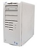
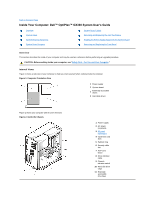
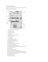
Back to Contents Page Inside Your Computer: Dell™ OptiPlex™ GX300 System User's Guide Overview Internal Views System Board Components System Board Jumpers System Board Labels Removing and Replacing the AGP Card Brace Rotating the Power Supply Away From the System Board Removing and Replacing the Front Bezel Overview This section describes the inside of your computer and may be used as a reference before performing an upgrade procedure. CAUTION: Before working inside your computer, see "Safety First-For You and Your Computer." Internal Views Figure 1 shows a side view of your computer to help you orient yourself when working inside the computer. Figure 1. Computer Orientation View 1 Power supply 2 System board 3 Externally accessible drives 4 Hard-disk drives Figure 2 shows your computer with its cover removed. Figure 2. Inside the Chassis 1 Power supply 2 AC power receptacle 3 I/O panel connectors 4 expansion card slots 5 Padlock ring 6 Security cable slot 7 AGP card brace 8 Drive interface cable 9 Chassis intrusion switch 10 Hard-disk drive cage 11 Externally accessible drive bays
-
 1
1 -
2
-
3
-
4
-
5
-
6
-
7
-
8
-
9
-
10
-
11
-
12
-
13
-
14
-
15
-
16
-
17
-
18
-
19
-
20
-
21
-
22
-
23
-
24
-
25
-
26
-
27
-
28
-
29
-
30
-
 31
31 -
 32
32 -
 33
33 -
 34
34 -
 35
35 -
 36
36 -
 37
37 -
 38
38 -
 39
39 -
 40
40 -
 41
41 -
42
-
43
-
44
-
45
-
46
-
47
-
48
-
49
-
50
-
51
-
52
-
53
-
54
-
55
-
56
-
57
-
58
-
59
-
60
-
61
-
62
-
63
-
64
-
65
-
66
-
67
-
68
-
69
-
70
-
71
-
72
-
73
-
74
-
75
-
76
-
77
-
78
-
79
-
80
-
81
-
82
-
83
-
84
-
85
-
86
-
87
-
88
-
89
-
90
-
91
 |
 |
