Dell OptiPlex GX300 User Guide - Page 67
Controls and Indicators
 |
View all Dell OptiPlex GX300 manuals
Add to My Manuals
Save this manual to your list of manuals |
Page 67 highlights
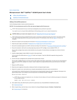
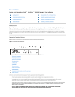
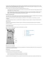
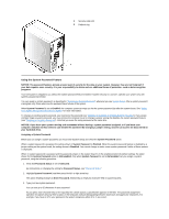
The NIC includes a Remote Wakeup feature that enables the computer to be started by a special local area network (LAN) signal from a server management console. Remote Wakeup provides remote computer setup, software downloading and installation, file updates, and asset tracking after hours and on weekends when LAN traffic is typically at a minimum. The NIC connector on the computer's back panel has the following indicators (see Figure 1): l A yellow activity indicator flashes when the system is transmitting or receiving network data. (A high volume of network traffic may make this indicator appear to be in a steady "on" state.) l A dual-colored link integrity and speed indicator, which lights up green when there is a good connection between a 10-Mbps network and the NIC, or it lights up orange when there is a good connection between a 100-Mbps network and the NIC. When the orange or green indicator is off, the computer is not detecting a physical connection to the network. Network Cable Requirements Your computer's NIC connector (an RJ45 connector located on the back panel) is designed for attaching an unshielded twisted pair (UTP) Ethernet cable. Press one end of the UTP cable into the NIC connector until the cable snaps securely into place. Connect the other end of the cable to an RJ45 jack wall plate or to an RJ45 port on a UTP concentrator or hub, depending on your network configuration. A 100-Mbps network requires Category 5 wiring and connectors. A 10-Mbps network requires Category 3 or Category 5 wiring and connectors. Video Connector The system uses a 15-pin high-density D-subminiature connector on the back panel for attaching a video graphics array (VGA)-compatible monitor to your system. Controls and Indicators Figure 2 shows the controls and indicators located on the front panel of your computer. Figure 2. Controls and Indicators 1 Diskette-drive access indicator 2 Power button 3 Power indicator 4 Reset button 5 Hard-disk drive access indicator 6 Cover release button Diskette-Drive Access Indicator The diskette-drive access indicator lights up when the drive is reading data from or writing data to a diskette. Wait until the access indicator turns off before removing a diskette from the drive. Power Button The power button controls the system's AC input power. For Microsoft Windows 95, the power button functions as follows: l When the computer is turned off, pushing the power button turns on the computer. l When the computer is turned on, pushing the power button turns off the computer. For Microsoft Windows 98 and Windows NT, you can configure the power button's function through the basic input/output system (BIOS). If you
-
 1
1 -
2
-
3
-
4
-
5
-
6
-
7
-
8
-
9
-
10
-
11
-
12
-
13
-
14
-
15
-
16
-
17
-
18
-
19
-
20
-
21
-
22
-
23
-
24
-
25
-
26
-
27
-
28
-
29
-
30
-
31
-
32
-
33
-
34
-
35
-
36
-
37
-
38
-
39
-
40
-
41
-
42
-
43
-
44
-
45
-
46
-
47
-
48
-
49
-
50
-
51
-
52
-
53
-
54
-
55
-
56
-
57
-
58
-
59
-
60
-
61
-
 62
62 -
 63
63 -
 64
64 -
 65
65 -
 66
66 -
 67
67 -
 68
68 -
 69
69 -
 70
70 -
 71
71 -
 72
72 -
73
-
74
-
75
-
76
-
77
-
78
-
79
-
80
-
81
-
82
-
83
-
84
-
85
-
86
-
87
-
88
-
89
-
90
-
91
 |
 |