Dell OptiPlex GX300 User Guide - Page 62
Microprocessor: Dell™ OptiPlex™ GX300 System User's Guide - vrm
 |
View all Dell OptiPlex GX300 manuals
Add to My Manuals
Save this manual to your list of manuals |
Page 62 highlights
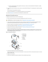
Back to Contents Page Microprocessor: Dell™ OptiPlex™ GX300 System User's Guide Adding a Second Microprocessor Upgrading an Existing Microprocessor Adding a Second Microprocessor Use the following procedure to add a second microprocessor. NOTICE: The second processor must be of the same type and speed as the first processor. NOTES: Dell recommends that only a technically knowledgeable person perform this procedure. Your system must be running the Microsoft® Windows NT® operating system to use a second microprocessor. CAUTION: Before you remove the computer cover, see "Safety First-For You and Your Computer." NOTE: Before disconnecting a peripheral from the system or removing a component from the system board, verify that the standby power light-emitting diode (LED) on the system board has turned off. For the location of this LED, see Figure 3 in "Inside Your Computer." 1. Remove the computer cover according to the instructions in "Removing and Replacing the Computer Cover." 2. Rotate the power supply as described in "Rotating the Power Supply Away From the System Board." 3. Remove the accelerated graphics port (AGP) card brace according to the instructions in "Removing and Replacing the AGP Card Brace." 4. Remove the terminator card from the secondary single-edge connector (SEC) cartridge connector (labeled "PROC_1"). Press the SEC cartridge release latches inward until they snap into position. Pull the terminator card straight out to remove it from the connector. 5. Install the voltage regulator module (VRM) in its socket on the system board. For the location of the VRM socket, see Figure 3 in "Inside Your Computer." Orient the VRM with its capacitors facing toward the power supply. 6. Insert the new SEC cartridge/heat sink assembly into the system board connector. Press the SEC cartridge firmly into its connector until it is fully seated and the latches snap into place. You must use up to 25 pounds (lb) of force to fully seat the SEC cartridge in its connector. Install or replace the two large thumbscrews that secure the heat sink to the system board. 7. Replace the AGP card brace. 8. Rotate the power supply back into position, making sure that the securing tab snaps into place. 9. Replace the computer cover, and reconnect your computer and peripherals to their power sources and turn them on. As the system boots, it detects the presence of the new processor and automatically changes the system configuration information in the System Setup program. If you installed a second microprocessor, the following message is displayed: Second processor detected NOTE: After you remove and replace the cover, the chassis intrusion detector will cause the following message to be displayed at the next system start-up: ALERT! Cover was previously removed. 10. Enter System Setup, and confirm that the top line in the system data area correctly identifies the installed processor(s). See "Using System Setup." 11. While in System Setup, reset the chassis intrusion detector by changing Chassis Intrusion to Enabled or Enabled-Silent. See "Chassis Intrusion" for instructions.
-
 1
1 -
2
-
3
-
4
-
5
-
6
-
7
-
8
-
9
-
10
-
11
-
12
-
13
-
14
-
15
-
16
-
17
-
18
-
19
-
20
-
21
-
22
-
23
-
24
-
25
-
26
-
27
-
28
-
29
-
30
-
31
-
32
-
33
-
34
-
35
-
36
-
37
-
38
-
39
-
40
-
41
-
42
-
43
-
44
-
45
-
46
-
47
-
48
-
49
-
50
-
51
-
52
-
53
-
54
-
55
-
56
-
 57
57 -
 58
58 -
 59
59 -
 60
60 -
 61
61 -
 62
62 -
 63
63 -
 64
64 -
 65
65 -
 66
66 -
 67
67 -
68
-
69
-
70
-
71
-
72
-
73
-
74
-
75
-
76
-
77
-
78
-
79
-
80
-
81
-
82
-
83
-
84
-
85
-
86
-
87
-
88
-
89
-
90
-
91
 |
 |