Dell OptiPlex GX300 User Guide - Page 29
Attaching Hard-Disk Drive Cables
 |
View all Dell OptiPlex GX300 manuals
Add to My Manuals
Save this manual to your list of manuals |
Page 29 highlights
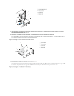
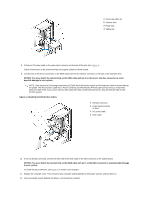
1 Drive-cage slide rail 2 Chassis slots 3 Hinge tabs 4 Sliding tab 8. Connect a DC power cable to the power input connector on the back of the drive (see Figure 4). Check all connectors to be certain that they are properly cabled and firmly seated. 9. Connect one of the device connectors on the EIDE cable to the 40-pin interface connector on the back of the hard-disk drive. NOTICE: You must match the colored strip on the EIDE cable with pin 1 on the drive's interface connector to avoid possible damage to your system. NOTE: Ultra Advanced Technology Attachment (ATA)/66 hard-disk drives require an 80-conductor cable to transfer data at full speed. The 80-conductor cable has a 40-pin connector just like the Ultra ATA/33 cable but has twice as many wires within the cable itself. If you use an Ultra ATA/33 cable with Ultra ATA/66 hard-disk drives, they will transfer data at Ultra ATA/33 speeds. Figure 4. Attaching Hard-Disk Drive Cables 1 Interface connector 2 Power input connector on drive 3 DC power cable 4 EIDE cable 10. If it is not already connected, connect the other end of the EIDE cable to the IDE1 connector on the system board. NOTICE: You must match the colored strip on the EIDE cable with pin 1 on the IDE1 connector to avoid possible damage to your system. To locate the IDE1 connector, see Figure 3 in "Inside Your Computer." 11. Replace the computer cover. Then reconnect your computer and peripherals to their power sources, and turn them on. 12. Insert a bootable system diskette into drive A, and restart the computer.
-
 1
1 -
2
-
3
-
4
-
5
-
6
-
7
-
8
-
9
-
10
-
11
-
12
-
13
-
14
-
15
-
16
-
17
-
18
-
19
-
20
-
21
-
22
-
23
-
 24
24 -
 25
25 -
 26
26 -
 27
27 -
 28
28 -
 29
29 -
 30
30 -
 31
31 -
 32
32 -
 33
33 -
 34
34 -
35
-
36
-
37
-
38
-
39
-
40
-
41
-
42
-
43
-
44
-
45
-
46
-
47
-
48
-
49
-
50
-
51
-
52
-
53
-
54
-
55
-
56
-
57
-
58
-
59
-
60
-
61
-
62
-
63
-
64
-
65
-
66
-
67
-
68
-
69
-
70
-
71
-
72
-
73
-
74
-
75
-
76
-
77
-
78
-
79
-
80
-
81
-
82
-
83
-
84
-
85
-
86
-
87
-
88
-
89
-
90
-
91
 |
 |
