Dell PowerEdge M520 Dell PowerConnect M6220/M6348/M8024 Switches Configuration - Page 135
CoS Mapping and Queue Configuration, the diagram
 |
View all Dell PowerEdge M520 manuals
Add to My Manuals
Save this manual to your list of manuals |
Page 135 highlights
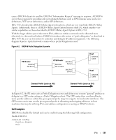
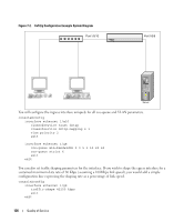
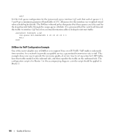
Figure 7-1. CoS Mapping and Queue Configuration packet A UserPri=3 packet B UserPri=7 packet C (untagged) packet D UserPri=6 Ingress PPoorrtt11//g01/100 mode='trust dot1p' 802.1p->COS Q Map 02 10 21 35 44 55 65 76 port default priority->traffic class 21 Egress Forward via switch fabric to egress PPoorrtt11/x0//g88 Port 1/0/8 Q6 B strict Q5 D A weighted 20% Q4 weighted 10% Q3 weighted 5% Q2 weighted 5% Q1 C weighted 0% Q0 weighted 0% Packet Transmission order: B, A, D, C Continuing this example, you configured the egress Port 1/g8 for strict priority on queue 6, and a set a weighted scheduling scheme for queues 5-0. Assuming queue 5 has a higher weighting than queue 1 (relative weight values shown as a percentage, with 0% indicating the bandwidth is not guaranteed), the queue service order is 6 followed by 5 followed by 1. Assuming each queue unloads all packets shown in the diagram, the packet transmission order as seen on the network leading out of Port 1/g8 is B, A, D, C. Thus, packet B, with its higher user precedence than the others, is able to work its way through the device with minimal delay and is transmitted ahead of the other packets at the egress port. Quality of Service 135
-
 1
1 -
2
-
3
-
4
-
5
-
6
-
7
-
8
-
9
-
10
-
11
-
12
-
13
-
14
-
15
-
16
-
17
-
18
-
19
-
20
-
21
-
22
-
23
-
24
-
25
-
26
-
27
-
28
-
29
-
30
-
31
-
32
-
33
-
34
-
35
-
36
-
37
-
38
-
39
-
40
-
41
-
42
-
43
-
44
-
45
-
46
-
47
-
48
-
49
-
50
-
51
-
52
-
53
-
54
-
55
-
56
-
57
-
58
-
59
-
60
-
61
-
62
-
63
-
64
-
65
-
66
-
67
-
68
-
69
-
70
-
71
-
72
-
73
-
74
-
75
-
76
-
77
-
78
-
79
-
80
-
81
-
82
-
83
-
84
-
85
-
86
-
87
-
88
-
89
-
90
-
91
-
92
-
93
-
94
-
95
-
96
-
97
-
98
-
99
-
100
-
101
-
102
-
103
-
104
-
105
-
106
-
107
-
108
-
109
-
110
-
111
-
112
-
113
-
114
-
115
-
116
-
117
-
118
-
119
-
120
-
121
-
122
-
123
-
124
-
125
-
126
-
127
-
128
-
129
-
 130
130 -
 131
131 -
 132
132 -
 133
133 -
 134
134 -
 135
135 -
 136
136 -
 137
137 -
 138
138 -
 139
139 -
 140
140 -
141
-
142
-
143
-
144
-
145
-
146
-
147
-
148
-
149
-
150
-
151
-
152
-
153
-
154
-
155
-
156
-
157
-
158
 |
 |
