Dell PowerEdge M520 Dell PowerConnect M6220/M6348/M8024 Switches Configuration - Page 81
For IPv4: Define an OSPF router. Define Area 1 as a stub. Enable OSPF for IPv4 on VLANs 10
 |
View all Dell PowerEdge M520 manuals
Add to My Manuals
Save this manual to your list of manuals |
Page 81 highlights
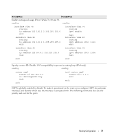
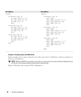
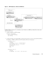
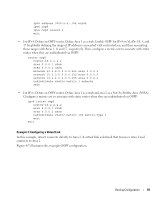
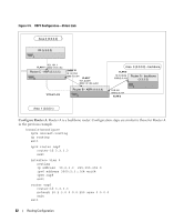
ipv6 address 3000:2:4::/64 eui64 ipv6 ospf ipv6 ospf areaid 2 exit • For IPv4: Define an OSPF router. Define Area 1 as a stub. Enable OSPF for IPv4 on VLANs 10, 5, and 17 by globally defining the range of IP addresses associated with each interface, and then associating those ranges with Areas 1, 0, and 17, respectively. Then, configure a metric cost to associate with static routes when they are redistributed via OSPF: router ospf router-id 2.2.2.2 area 0.0.0.1 stub area 0.0.0.2 nssa network 10.1.2.0 0.0.0.255 area 0.0.0.1 network 10.2.3.0 0.0.0.255 area 0.0.0.0 network 10.2.4.0 0.0.0.255 area 0.0.0.2 redistribute static metric 1 subnets exit • For IPv6: Define an OSPF router. Define Area 1 as a stub and area 2 as a Not-So-Stubby-Area (NSSA). Configure a metric cost to associate with static routes when they are redistributed via OSPF: ipv6 router ospf router-id 2.2.2.2 area 0.0.0.1 stub area 0.0.0.2 nssa redistribute static metric 105 metric-type 1 exit exit Example 3: Configuring a Virtual Link In this example, Area 0 connects directly to Area 1. A virtual link is defined that traverses Area 1 and connects to Area 2. Figure 4-5 illustrates this example OSPF configuration. Routing Configuration 81
-
 1
1 -
2
-
3
-
4
-
5
-
6
-
7
-
8
-
9
-
10
-
11
-
12
-
13
-
14
-
15
-
16
-
17
-
18
-
19
-
20
-
21
-
22
-
23
-
24
-
25
-
26
-
27
-
28
-
29
-
30
-
31
-
32
-
33
-
34
-
35
-
36
-
37
-
38
-
39
-
40
-
41
-
42
-
43
-
44
-
45
-
46
-
47
-
48
-
49
-
50
-
51
-
52
-
53
-
54
-
55
-
56
-
57
-
58
-
59
-
60
-
61
-
62
-
63
-
64
-
65
-
66
-
67
-
68
-
69
-
70
-
71
-
72
-
73
-
74
-
75
-
 76
76 -
 77
77 -
 78
78 -
 79
79 -
 80
80 -
 81
81 -
 82
82 -
 83
83 -
 84
84 -
 85
85 -
 86
86 -
87
-
88
-
89
-
90
-
91
-
92
-
93
-
94
-
95
-
96
-
97
-
98
-
99
-
100
-
101
-
102
-
103
-
104
-
105
-
106
-
107
-
108
-
109
-
110
-
111
-
112
-
113
-
114
-
115
-
116
-
117
-
118
-
119
-
120
-
121
-
122
-
123
-
124
-
125
-
126
-
127
-
128
-
129
-
130
-
131
-
132
-
133
-
134
-
135
-
136
-
137
-
138
-
139
-
140
-
141
-
142
-
143
-
144
-
145
-
146
-
147
-
148
-
149
-
150
-
151
-
152
-
153
-
154
-
155
-
156
-
157
-
158
 |
 |